


- Introduction
- Maintenance
- Preparation
- Service specifications
- Diagnostics
- 2JZ-GE Engine
- 2JZ-GTE Engine
- 2JZ-GTE Turbocharging
- 2JZ-GE Emission control
- 2JZ-GTE Emission control
- 2JZ-GE SFI
- 2JZ-GTE SFI
- Cooling
- Lubrication
- Ignition system 2JZ-GE
- Ignition system 2JZ-GTE
- Starting system
- Charging system
- Clutch
- W58 manual transmission
- V160 manual transmission
- A340E 2JZ-GE automatic transmission
- A340E 2JZ-GTE automatic transmission
- Propeller shaft
- Suspension and axle
- Brake system
- Steering
- Supplemental restraint system
- Body electrical system
- Body
- Air conditioning system

TOYOTA hand-held tester only:
Compared to the normal mode, the check mode has an increased sensitivity to detect malfunctions.
Furthermore, the same diagnostic items which are detected in the normal mode can also be detected in the check mode.
If any of the following codes is recorded, the ECM enters fail-safe mode.
Diagnosis system
- Description
When troubleshooting OBD II vehicles, the only difference from the usual troubleshooting procedure is that you connect to the vehicle the OBD II scan tool complying with SAE J1978 or TOYOTA hand-held tester, and read off various data output from the vehicle’s ECM. OBD II regulations require that the vehicle’s on-board computer lights up the Malfunction Indicator Lamp (MIL) on the instrument panel when the computer detests a malfunction in the computer itself or in drive system components which affect vehicle emissions. In addition to the MIL lighting up when a malfunction is detected, the applicable Diagnostic Trouble Codes (DTC) prescribed by SAE J2012 are recorded in the ECM memory.
(See page DI-14 )
If the malfunction does not reoccur in 3 trips, the MIL goes off but the DTC remain recorded in the ECM memory. To check the DTC, connect the OBD II scan tool or TOYOTA hand-held tester to Data Link Connector 3 (DLC3) on the vehicle. The OBD II scan tool or TOYOTA hand-held tester also enables you to erase the DTC and check freezed frame data and various forms of engine data. (For operating instructions, see the OBD II scan tool’s instruction book.)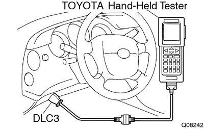 DTC include SAE controlled codes and Manufacturer controlled codes.
SAE controlled codes must be set as prescribed by the SAE, while Manufacturer controlled codes can be set freely by the manufacturer within the prescribed limits.
(See DTC chart on page DI-14 )
The diagnosis system operates in normal mode during normal vehicle use. It also has a check mode for technicians to simulate malfunction symptoms and troubleshoot. Most DTC use 2 trip detection logic* to prevent erroneous detection and ensure thorough malfunction detection. By switching the ECM to check mode when troubleshooting, the technician can cause the MIL to light up for a malfunction that is only detected once or momentarily. (TOYOTA hand-held tester only)
(See page DI-3 )
*2 trip detection logic: When a logic malfunction is first detected, the malfunction is temporarily stored in the ECM memory. If the same malfunction is detected again during the second drive test, this second detection causes the MIL to light up.
The 2 trip repeats the same mode a 2nd time. (However, the IG switch must be turned OFF between the 1st trip and 2nd trip).
Freeze frame data:
Freeze frame data records the engine condition when a misfire (DTC P0300 - P0306) or fuel trim malfunction (DTC P0171, P0172), or other malfunction (first malfunction only), is detected.
Because freeze frame data records the engine conditions (fuel system, calculator load, engine coolant temperature, fuel trim, engine speed, vehicle speed, etc.) when the malfunction is detected, when troubleshooting it is useful for determining whether the vehicle was running orstopped, the engine warmed up or not, the air-fuel ratio lean or rich, etc. at the time of the malfunction.
Priorities for Troubleshooting:
If troubleshooting priorities for multiple DTC are given in the applicable diagnostic chart, these should be followed. If no instructions are given, troubleshoot DTC according to the following priorities.- DTC other than fuel trim malfunction (DTC P0171, P0172), EGR (DTC P0401, P0402), and misfire (DTC P0300 - P0306).
- Fuel trim malfunction (DTC P0171, P0172) and EGR (DTC P0401, P0402).
- Misfire (DTC P0300 - P0306).
- Check the DLC3.
The vehicle’s ECM uses V.P.W. (Variable Pulse Width) for communication to comply with SAE J1850. The terminal arrangement of DLC3 complies with SAE J1962 and matches the V.P.W. format.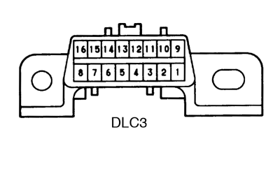
Terminal No. Connection / Voltage or Resistance Condition 2 Bus ⊕ Line / Pulse generation During transmission 4 Chassis Ground / ↔ Body Ground 1 Ω or less Always 5 Signal Ground / ↔ Body Ground 1 Ω or less Always 16 Battery Positive / ↔ Body Ground 9 - 14 V Always If your display shows ”UNABLE TO CONNECT TO VEHICLE” when you have connected the cable of the OBD II scan tool or TOYOTA hand-held tester to DLC3, turned the ignition switch ON and operated the scan tool, there is a problem on the vehicle side or tool side.- If communication is normal when the tool is connected to another vehicle, inspect DLC3 on the original vehicle.
- If communication is still not possible when the tool is connected to another vehicle, the problem is probably in the tool itself, so consult the Service Department listed in the tool’s instruction manual.
Inspect diagnosis (Normal mode)
- Check the MIL.
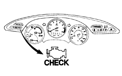
- The MIL comes on when the ignition switch is turned ON and the engine is not running. If the MIL does not light up, troubleshoot the combination meter (See page BE-40 ).
- When the engine is started, the MIL should go off. If the lamp remains on, the diagnosis system has detected a malfunction or abnormality in the system.
- The MIL comes on when the ignition switch is turned ON and the engine is not running.
- Check the DTC. (TOYOTA hand-held tester only): When the diagnosis system is switched from normal mode to check mode, it erases all DTC and freezed frame data recorded in normal mode. So before switching modes, always check the DTC and freezed frame data, and note them down.
- Prepare the OBD II scan tool (complying with SAE J1978) or TOYOTA hand-held tester.
- Connect the OBD II scan tool or TOYOTA hand-held tester to DLC3 at the lower left of the instrument panel.
- Turn the ignition switch ON and turn the OBD II scan tool or TOYOTA hand-held tester switch ON.
- Use the OBD II scan tool or TOYOTA hand-held tester to check the DTC and freezed frame data, note them down. (For operating instructions, see the OBD II scan tool’s instruction book.)
- See page DI-14 to confirm the details of the DTC.
When simulating symptoms with an OBD II scan tool (excluding TOYOTA hand-held tester) to check the DTC, use normal mode. For codes on the DTC chart subject to ”2 trip detection logic”, turn the ignition switch OFF after the symptom is simulated the first time. Then repeat the simulation process again. When the problem has been simulated twice, the MIL lights up and the DTC are recorded in the ECM.
Inspect diagnosis (Check Mode)
TOYOTA hand-held tester only:
Compared to the normal mode, the check mode has an increased sensitivity to detect malfunctions.
Furthermore, the same diagnostic items which are detected in the normal mode can also be detected in the check mode.
- Check the DTC.
- Initial conditions.
- Battery positive voltage 11V or more.
- Throttle valve fully closed.
- Transmission in park or neutral position.
- Air conditioning switched OFF.
- Turn ignition switch OFF.
- Prepare the TOYOTA hand-held tester.
- Connect the TOYOTA hand-held tester to DLC3 at the lower left of the instrument panel.
- Turn the ignition switch ON and switch the TOYOTA hand-held tester ON.
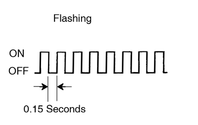
- Switch the TOYOTA hand-held tester normal mode to check mode. (Check that the MIL flashes.)
- Start the engine. (The MIL goes out after the engine start.)
- Simulate the conditions of the malfunction described by the customer. Leave the ignition switch ON until you have checked the DTC, etc.
- After simulating the malfunction conditions, use the TOYOTA hand-held tester diagnosis selector to check the DTC and freezed frame data, etc. Take care not to turn the ignition switch OFF. Turning the ignition switch OFF switches the diagnosis system from check mode to normal mode, so all DTC, etc. are erased.
- After checking the DTC, inspect the applicable circuit.
- Initial conditions.
- Clear the DTC.
The following actions will erase the DTC and freezed frame data.- Operating the OBD II scan tool (complying with SAE J1978) or TOYOTA hand-held tester to erase the codes. (See the OBD II scan tool’s instruction book for operating instructions.)
- Disconnecting the battery terminals or EFI fuse. If the TOYOTA hand-held tester switches the ECM from normal mode to check mode or vice-versa, or if the ignition switch is turned from ON to ACC or OFF during check mode, the DTC and freezed frame data will be erased.
Fail-safe chart
If any of the following codes is recorded, the ECM enters fail-safe mode.
| DTC No. | Fail-Safe Operation | Fail-safe Deactivation Conditions |
| P0100 | Ignition timing fixed at 5° BTDC Injection time fixed CTP Switch ON ......... 3.6 m sec. CTP Switch OFF ....... 6.7 m sec. | Returned to normal condition |
| P0110 | Intake air temp. is fixed at 20°C (68°F) | Returned to normal condition |
| P0115 | Engine coolant temp. is fixed at 80°C (176°F) | Returned to normal condition |
| P0120 | VTA is fixed at 0° | The following condition must be repeated at least 2 times consecutively When closed throttle position switch is ON: 0.1 V ≤ VTA ≤ 0.95 V |
| P0135 P0141 P0155 | The heater circuit in which an abnormality is detected is turned off | Ignition switch OFF |
| P0325 P0330 | Max. timing retardation | Ignition switch OFF |
| P1300 | Fuel cut | IGF signal is detected for 1 ignition |
| P1605 | Max. timing retardation | Returned to normal condition |
Check for intermittent problems
TOYOTA hand-held tester only:
By putting the vehicle’s ECM in check mode, 1 trip detection logic is possible instead of 2 trip detection logic and sensitivity to detect open circuits is increased. This makes it easier to detect intermittent problems.
- Clear diagnostic trouble codes (See page DI-3 )
- Set check mode (See page DI-3 )
- Perform a simulation test (See page IN-18 )
- Connector connection and terminal inspection (See page IN-28 )
- Visual check and contact pressure check (See page IN-28 )
- Connector handling (See page IN-28 )
Basic inspection
When the malfunction code is not confirmed in the DTC check, troubleshooting should be performed in the order for all possible circuits to be considered as the causes of the problems.
In many causes, by carrying out the basic engine check shown in the following flow chart, the location causing the problem can be found quickly and efficiently. Therefore, use of this check is essential in engine troubleshooting.
| 1 | Is battery positive voltage 11 V or more when engine is stopped? | ||
| NO > | Charge or replace battery. | ||
| YES | |||
| 2 | Is engine cranked? | ||
| NO > | Proceed to page ST-14 and continue to troubleshoot. | ||
| YES | |||
| 3 | Does engine start? | ||
| NO > | Go to step 7. | ||
| YES | |||
| 4 | Check are filter. | ||
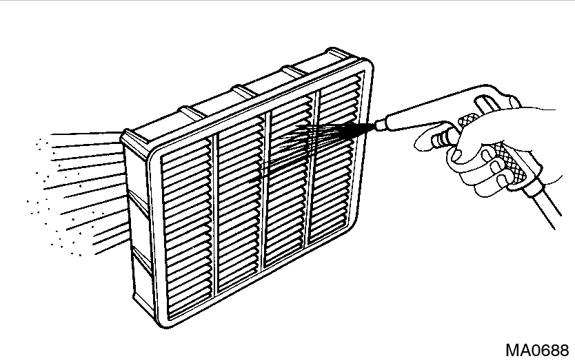 Preparation: Preparation: Remove air filter. Check: Visually check that the air cleaner element is not dirty or excessively oily. If necessary, clean element with compressed air. First blow from inside throughly, then blow from outside of element. | |||
| NG > | Repair or replace. | ||
| OK | |||
| 5 | Check idle speed. | ||
Preparation:
Use CURRENT DATA to check the engine idle speed. OK: Idle speed: 700 ± 50 rpm | |||
| NG > | Proceed to matrix chart of problem symptoms on page DI-24. | ||
| OK | |||
| 6 | Check ignition timing. | ||
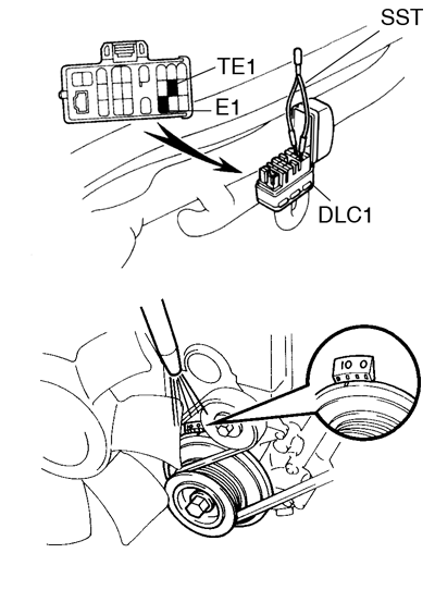 Preparation:A Preparation:A
Check ignition timing. OK: Ignition timing: 10° BTDC at idle | |||
| NG > | Proceed to IG-1 and continue to troubleshoot. | ||
| OK | |||
| Proceed to matrix chart of problem symptoms on page DI-24. | |||
| 7 | Check fuel pressure. | ||
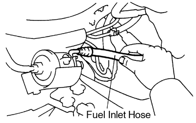 Preparation: Preparation:
Check for fuel pressure in the fuel inlet hose when it is pinched off. At this time, you will hear the sound of flowing. | |||
| NG > | Proceed to page SF-5 and continue to troubleshoot. | ||
| OK | |||
| 8 | Check for spark. | ||
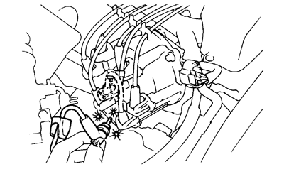 Preparation: Preparation:
Check if spark occurs while the engine is being cranked. To prevent excess fuel being injected from the injectors during this test, don’t crank the engine for more than 5 ∼ 10 sec. at a time. | |||
| NG > | Proceed to page IG-1 and continue totroubleshoot. | ||
| OK | |||
| Proceed to matrix chart of problem systems on page DI-24. | |||
Engine operating condition
The values given below for ”Normal Condition” are representative values, so a vehicle may still be normal even if its value varies from those listed here. So do not decide whether a part is faulty or not solely according to the ”Normal Condition” here.
- CARB Mandated Signals
TOYOTA hand-held tester display Measurement Item Normal Condition* FUEL SYS #1 Fuel System Bank 1
OPEN: Air-fuel ratio feedback stopped
CLOSED: Air-fuel ratio feedback operatingIdling after warmed up:
CLOSEDFUEL SYS #2 Fuel System Bank 2
OPEN: Air-fuel ratio feedback stopped
CLOSED: Air-fuel ratio feedback operatingIdling after warmed up:
CLOSEDCALC LOAD Calculator Load:
Current intake air volume as a proportion of max. intake air volumeIdling: 11.7 ∼ 21.1%
Racing without load (2,500 rpm): 10.6 ∼ 21.1%COOLANT TEMP Engine Coolant Temperature Sensor Value After warmed up:
80 - 95°C (176 - 203°F)SHORT FT #1 Short - term Fuel Trim Bank 1 0 ± 20% LONG FT #1 Long - term Fuel Trim Bank 1 0 ± 20% SHORT FT #2 Short - term Fuel Trim Bank 2 0 ± 20% LONG FT #2 Long - term Fuel Trim Bank 2 0 ± 20% ENGINE SPD Engine Speed Idling: 700 ± 50 rpm VEHICLE SPD Vehicle Speed Vehicle Stopped:
0 km/h (0 mph)IGN ADVANCE Ignition Advance
Ignition Timing of Cylinder No.1Idling: BTDC 12 - 25° INTAKE AIR Intake Air Temperature Sensor Valve Equivalent to Ambient Temp. MAF Air Flow Rate Through Mass Air Flow Meter Idling: 2.5 - 4.4 gm/sec
Racing without load (2,500 rpm):
7.9 - 15.8 gm/secTHROTTLE POS Voltage Output of Throttle Position Sensor Calculated as a Percentage 0 V → 0 %, 5 V → 100% Throttle
Fully Closed: 7 - 11 %
Fully Open: 65 - 75 %O2S B1, S1 Voltage Output of Oxygen Sensor Bank 1, Sensor 1 Idling: 0.1 - 0.9 V 02FT, B1, S1 Oxygen Sensor Fuel Trim Bank 1, Sensor 1 (Same as SHORT FT #1) 0 ± 20 % 02S, B1, S2 Voltage Output of Oxygen Sensor Bank 1, Sensor 2 Driving 50 km/h (31mph):
0.1 - 0.9 V02S, B2, S1 Voltage Output of Oxygen Sensor Bank 2, Sensor 1 Idling: 0.1 ∼ 0.9 V 02FT, B2, S1 Oxygen Sensor Fuel Trim Bank 2, Sensor 1 (Same as SHORT FT #2) 0 ± 20 %
This guide is based on the book edition Toyota (RM502U, 1997)