


- Introduction
- Maintenance
- Preparation
- Service specifications
- Diagnostics
- 2JZ-GE Engine
- 2JZ-GTE Engine
- 2JZ-GTE Turbocharging
- 2JZ-GE Emission control
- 2JZ-GTE Emission control
- 2JZ-GE SFI
- 2JZ-GTE SFI
- Cooling
- Lubrication
- Ignition system 2JZ-GE
- Ignition system 2JZ-GTE
- Starting system
- Charging system
- Clutch
- W58 manual transmission
- V160 manual transmission
- A340E 2JZ-GE automatic transmission
- A340E 2JZ-GTE automatic transmission
- Propeller shaft
- Suspension and axle
- Brake system
- Steering
- Supplemental restraint system
- Body electrical system
- Body
- Air conditioning system
- Remove engine under cover
- Drain engine coolant
- Remove air cleaner duct
- Remove air cleaner, MAF meter and intake air connector pipe assembly (See page EM-57)
- Remove drive belt (See page CH-8)
- Remove No.2 front exhaust pipe (See page CH-8)
- Remove exhaust manifold
- Disconnect the 2 heated oxygen sensor connectors.
- Using a 14 mm deep socket wrench, remove the 4 nuts, exhaust manifold and gasket. Remove the No.1 and No.2 exhaust manifolds.

- Remove water bypass outlet and No.1 water bypass pipe (See page CO-7 )
- Disconnect PS pump without disconnecting hoses
- Disconnect these hoses:
- PS air hose from No.4 timing belt cover
- PS air hose from air intake chamber

- Remove the 2 bolts, and disconnect the vane pump from the pump bracket. Put aside the vane pump, and suspend it.
- Disconnect these hoses:
- Disconnect fuel return hose
- Disconnect the fuel return hose from the fuel return pipe. Plug the hose end.
- Disconnect the fuel return hose from the oil dipstick guide.

- Remove engine wire bracket
- Remove the bolt and bracket, disconnect the engine wire from the intake manifold stay.
- Remove throttle body and intake air connector assembly (See page SF-19)
- Remove air intake chamber stays

- Remove the bolt, nut and No.1 stay.
- Remove the bolt, nut and No.2 stay.
- Remove oil dipstick and guide for engine (See page LU-9)

- Remove oil dipstick and guide for transmission (See page EM-57)
- Disconnect EGR Gas temperature sensor connector

- Disconnect the connector from No.2 vacuum pipe.
- Disconnect the sensor connector from the wiring connector.
- Remove No.2 vacuum pipe and VSV assembly
Remove the 2 nuts, and disconnect the vacuum pipe from the air intake chamber and intake manifold. - Remove vacuum control valve set
- Remove the 2 nuts, and disconnect the vacuum tank from the intake manifold.

- Disconnect these connector and hoses, and remove the vacuum control valve set:

- VSV connector
- Vacuum hose (from air intake chamber) from port B of vacuum tank
- Vacuum hose (from actuator) from VSV
- Remove the 2 nuts, and disconnect the vacuum tank from the intake manifold.
- Remove DLC1 bracket and VSV assembly
- Disconnect the connector and hoses:

- VSV connector
- Vacuum sensing hose from fuel pressure control
- Vacuum sensing hose from air intake chamber
- Remove the bolt, the DLC1 bracket and VSV assembly.
- Disconnect the connector and hoses:
- Remove air intake chamber

- Disconnect these hoses:
- Vacuum hose from brake booster union
- EVAP hose from No.2 vacuum pipe
- Remove the bolt holding the engine wire protector to the air intake chamber.
- Remove the 5 bolts, nut, air intake chamber and gasket.
- Disconnect these hoses:
- Remove No.3 timing belt cover

- Remove the oil filter cap.
- Using a 5 mm hexagon wrench, remove the 6 bolts and timing belt cover.
- Remove cylinder head rear cover
Using a 5 mm hexagon wrench, remove the 4 bolts and cylinder head rear cover. - Disconnect high-tension cords from cylinder head covers (See page IG-8)
- Remove distributor and high-tension cords assembly (See page IG-14)
- Remove spark plugs
- Remove timing belt from camshaft timing pulleys (See page EM-13 )
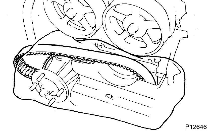
- Support the timing belt, so that the meshing of the crankshaft timing pulley and timing belt does not shaft.
- Be careful not to drop anything inside the timing belt cover.
- Do not allow the timing belt to come into contact with oil, water or dust.
- Disconnect engine wire

- Disconnect the wire clamp from the bracket.
- Disconnect these connectors:
- Heated oxygen sensor (bank 1 sensor 1) connector
- Crankshaft position sensor connector
- Remove the 2 bolts, and disconnect the 2 ground straps from the intake manifold.

- Disconnect the wire clamp from the fuel return pipe.
- Disconnect these connectors:
- ECT sensor connector
- ECT sender gauge connector
- 2 knock sensor connectors
- Oil pressure switch connector
- Oil level sensor connector
- A/C compressor connector
- 6 injector connectors
- Remove the 3 nuts, and disconnect the engine wire protector from the intake manifold.

- Remove water outlet with water bypass hose
- Disconnect the water bypass hose from the clamp on the oil filter bracket.
- Remove the 2 nuts, bolt and water outlet.

- Remove intake manifold stay
Remove the 2 bolts and manifold stay. - Remove fuel pressure pulsation damper (See page SF-29)

- Remove fuel inlet pipe
- Remove the clamp bolt from the intake manifold.
- Remove the union bolt, 2 gaskets and fuel inlet pipe.
- Remove intake manifold and delivery pipe assembly
Remove the 6 bolts, 2 nuts, the intake manifold, delivery pipe assembly and gasket.
- Remove No.3, No.1 and No.2 cylinder head covers

- Remove the PCV valve.
- Remove the 4 bolts, 4 nuts and No.3 cylinder head cover.
- Remove the 4 bolts, No.1 cylinder head cover and gasket.
- Remove the 4 bolts, No.2 cylinder head cover and gasket.
- Remove camshaft timing pulleys
Hold the hexagon portion of the camshaft with a wrench, and remove the pulley the pulley mounting bolt and camshaft pulley.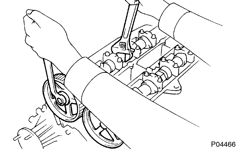
- Remove No.4 timing belt cover
Remove the 4 bolts and timing belt cover.
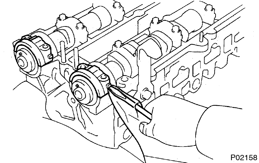
- Remove camshafts
- Uniformly loosen and remove the 4 No.1 bearing cap bolts.

- Using a screwdriver, pry out the 2 No.1 camshaft bearing caps and oil seals. Be careful not to damage the cap. Tape the screwdriver tip.
- Uniformly loosen and remove the 12 bearing cap bolts, in several passes, in the sequence shown, and remove the 6 bearing caps and camshaft.
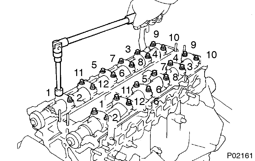
- Remove the intake and exhaust camshafts.
- Uniformly loosen and remove the 4 No.1 bearing cap bolts.
- Remove cylinder head
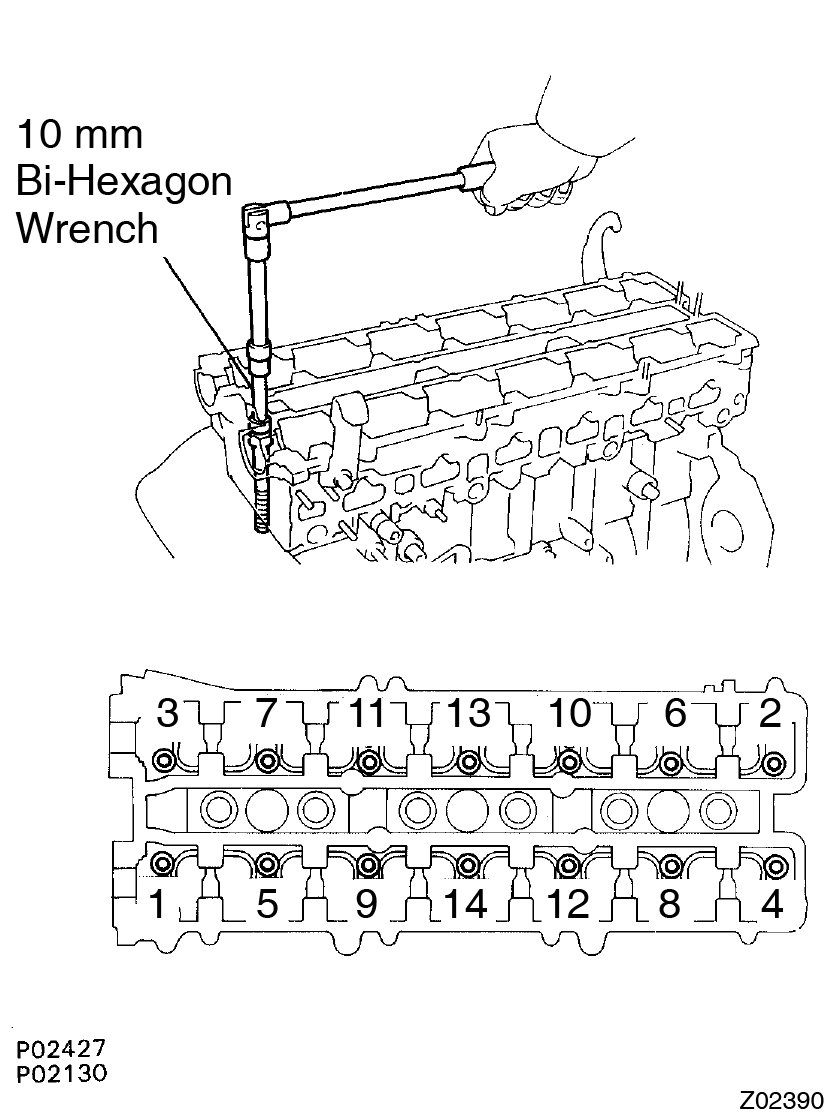
- Using a 10 mm bi-hexagon wrench, uniformly loosen and remove the 14 cylinder head bolts, in several passes, in the sequence shown. Cylinder head warpage or cracking could result from removing in incorrect order
- Remove the 14 plate washers.
- Lift the cylinder head from the dowels on the cylinder block.
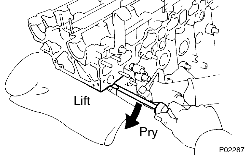
- Place the head on wooden blocks on a bench.
Be careful not to damage the contact surfaces of the cylinder head and cylinder block. - Using a 10 mm bi-hexagon wrench, uniformly loosen and remove the 14 cylinder head bolts, in several passes, in the sequence shown.
This guide is based on the book edition Toyota (RM502U, 1997)