


- Introduction
- Maintenance
- Preparation
- Service specifications
- Diagnostics
- 2JZ-GE Engine
- 2JZ-GTE Engine
- 2JZ-GTE Turbocharging
- 2JZ-GE Emission control
- 2JZ-GTE Emission control
- 2JZ-GE SFI
- 2JZ-GTE SFI
- Cooling
- Lubrication
- Ignition system 2JZ-GE
- Ignition system 2JZ-GTE
- Starting system
- Charging system
- Clutch
- W58 manual transmission
- V160 manual transmission
- A340E 2JZ-GE automatic transmission
- A340E 2JZ-GTE automatic transmission
- Propeller shaft
- Suspension and axle
- Brake system
- Steering
- Supplemental restraint system
- Body electrical system
- Body
- Air conditioning system
- Remove gasket material
Using a gasket scraper, remove all the gasket material from the cylinder block surface.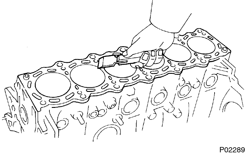
- Clean cylinder block
Using a soft brush and solvent, thoroughly clean the cylinder block. - Inspect cylinder block surface for flatness
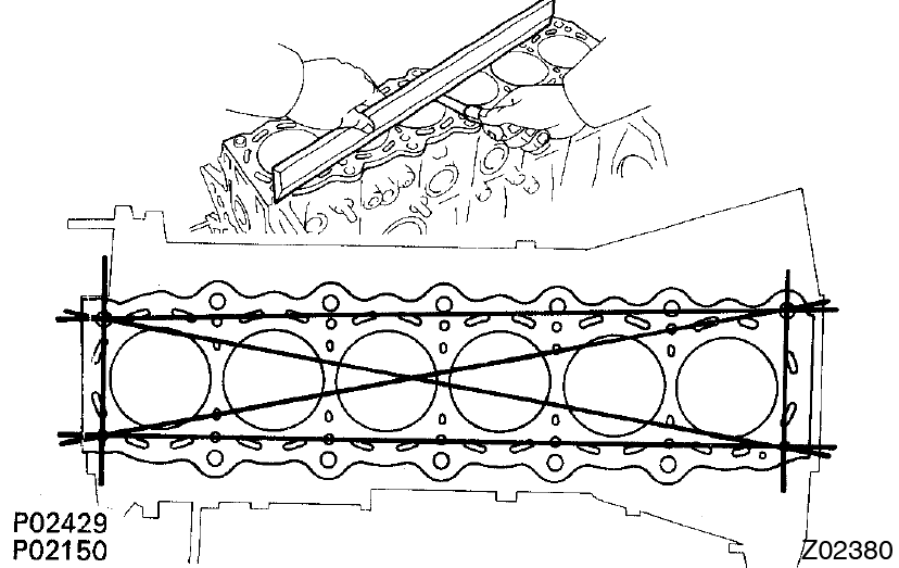 Using precision straight edge and feeler gauge, measure the surfaces of the cylinder block for warpage.
Maximum warpage: 0.07 mm (0.0028 in.)
If warpage is greater than maximum, replace the cylinder block. - Inspect cylinder for vertical scratches
 Visually check the cylinder for vertical scratches.
If deep scratches are present, replace the cylinder block. - Inspect cylinder bore diameter
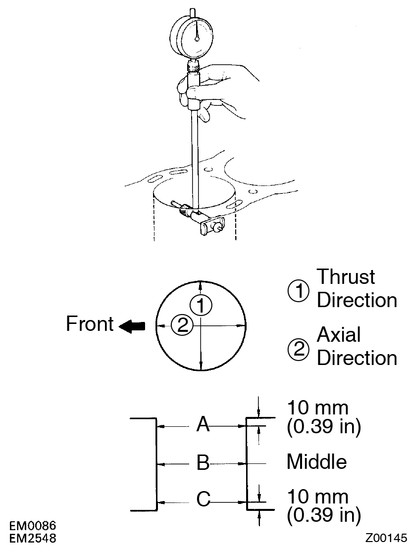 Using a cylinder gauge, measure the cylinder bore diameter at positions A, B and C in the thrust and axial directions.
Standard diameter:
86.000 - 86.013 mm (3.3858 - 3.3863 in.)
Maximum diameter: 86.02 mm (3.3866 in.)
If the diameter is greater than maximum, replace the cylinder block. - Remove cylinder ridge
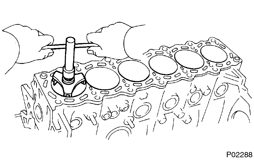 If the wear is less than 0.2 mm (0.008 in.), using a ridge reamer, grind the top of the cylinder.
 - Inspect main bearing cap bolts
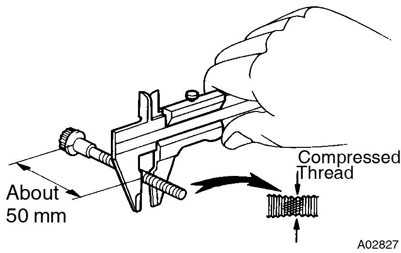 Using vernier calipers, measure the minimum diameter of the compressed thread at the measuring point.
Standard diameter:
9.96 - 9.97 mm (0.3921 - 0.3925 in.)
Minimum diameter: 9.7 mm (0.382 in.)
If the diameter is less than minimum, replace the bolt. - Clean piston
- Using a gasket scraper, remove the carbon from the piston top.

- Using a groove cleaning tool or broken ring, clean the piston ring grooves.
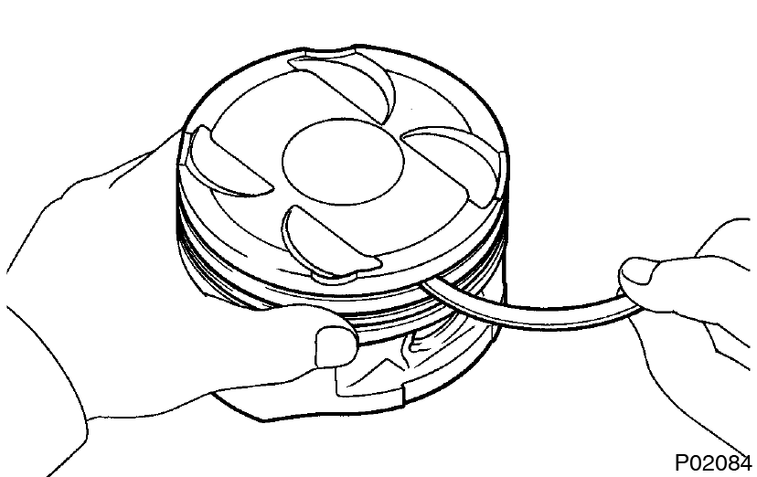
- Using solvent and a brush, thoroughly clean the piston. Do not use a wire brush.
- Using a gasket scraper, remove the carbon from the piston top.
- Inspect piston oil clearance
- Using a micrometer, measure the piston diameter at right angles to the piston pin center line, 34 mm (1.34 in.) from the piston head.
Piston diameter:
85.917 - 85.927 mm (3.3826 - 3.3830 in.)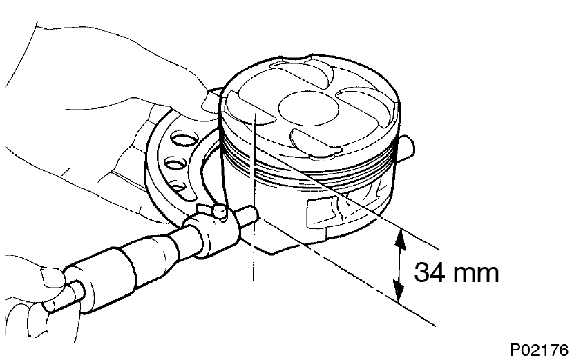
- Measure the cylinder bore diameter in the thrust directions. (See step 5)
- Subtract the piston diameter measurement from the cylinder bore diameter measurement.
Standard oil clearance:
0.073 - 0.096 mm (0.0029 - 0.0038 in.)
Maximum oil clearance:
0.12 mm (0.0047 in.)
If the oil clearance is greater than maximum, replace all the 6 pistons. If necessary, replace the cylinder block.
- Using a micrometer, measure the piston diameter at right angles to the piston pin center line, 34 mm (1.34 in.) from the piston head.
- Inspect piston ring groove clearance
 Using a feeler gauge, measure the clearance between new piston ring and the wall of the piston ring groove.
Ring groove clearance:
No.1 0.040 - 0.080 mm (0.0016 - 0.0031 in.)
No.2 0.030 - 0.070 mm (0.0012 - 0.0028 in.)
If the clearance is not as specified, replace the piston. - Inspect piston ring end GAP
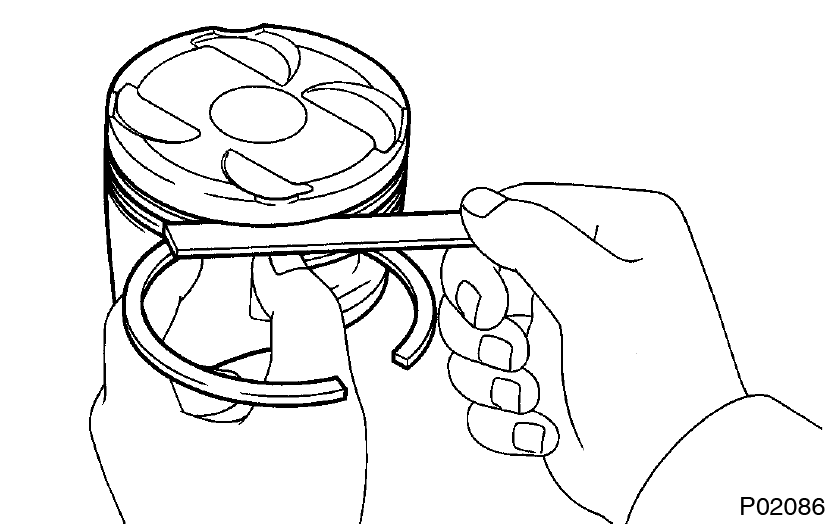
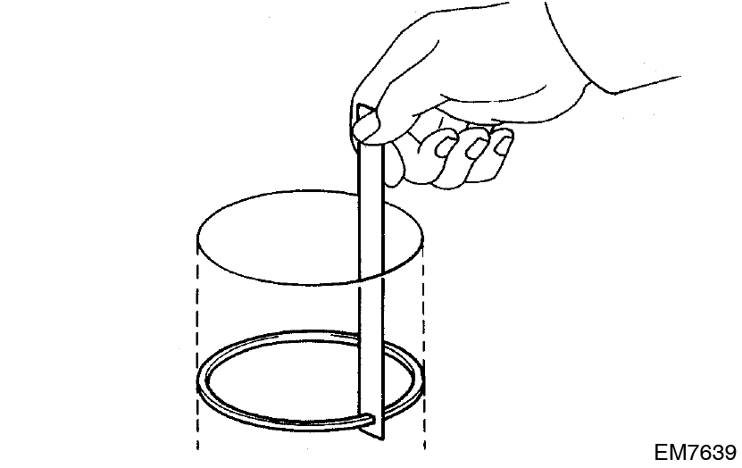
- Insert the piston ring into the cylinder bore.
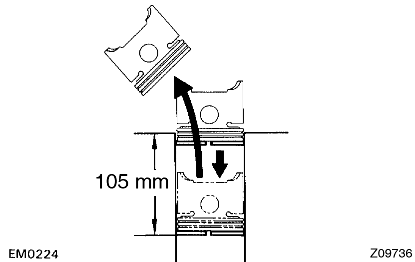
- Using a piston, push the piston ring a little beyond the bottom of the ring travel, 105 mm (4.13 in.) from the top of the cylinder block.
- Using a feeler gauge, measure the ring end gap.
 Ring end gap: If the end gap is greater than maximum, replace the piston ring.
Piston ring STD mm (in.) Maximum mm (in.) No.1 0.300 - 0.400 (0.0118 - 0.0157) 1.000 (0.0394) No.2 0.350 - 0.450 (0.0138 - 0.0178) 1.050 (0.0413) Oil (Side rail) 0.130 - 0.380 (0.0051 - 0.0150) 0.980 (0.0386)
If the end gap is greater than maximum, even with a new piston ring, replace the cylinder block.
- Insert the piston ring into the cylinder bore.
- Pinspect piston pin fit
 At 80°C (176°F), you should be able to push the piston pin into the piston pin hole with your thumb.
 - Inspect connecting ROD alignment
Using a feeler gauge and rod aligner, check the connecting rod alignment.- Check for out-of-alignment
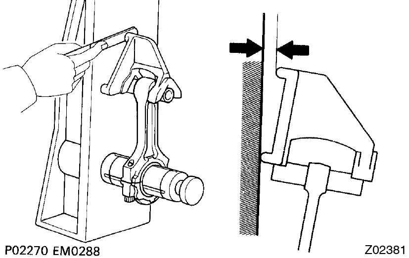 Maximum out-of-alignment:
0.05 mm (0.0020 in.) per 100 mm (3.94 in.)
If out-of-alignment is greater than maximum, replace the connecting rod assembly. - Check for twist
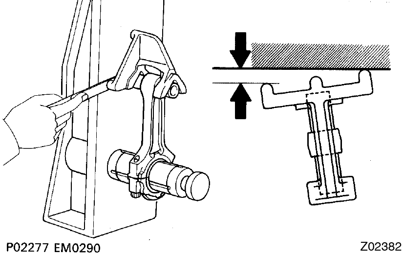 Maximum twist:
0.15 mm (0.0059 in.) per 100 mm (3.94 in.)
If twist is greater than maximum, replace the connecting rod assembly.
- Check for out-of-alignment
- Inspect piston pin oil clearance
- Using a caliper gauge, measure the inside diameter of the connecting rod bushing.
Bushing inside diameter:
22.005 - 22.014 mm (0.8663 - 0.8667 in.)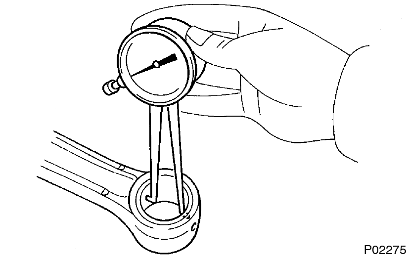
- Using a micrometer, measure the piston pin diameter.
Piston pin diameter:
21.997 - 22.006 mm (0.8660 - 0.8664 in.) - Subtract the piston pin diameter measurement from the bushing inside diameter measurement.
Standard oil clearance:
0.005 - 0.011 mm (0.0002 - 0.0004 in.)
Maximum oil clearance:
0.05 mm (0.0020 in.)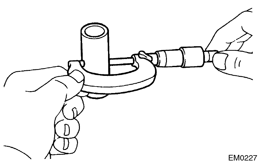 If the oil clearance is greater than maximum, replace the bushing. If necessary, replace the piston and piston pin as a set.
 - Check the piston pin fit at room temperature.
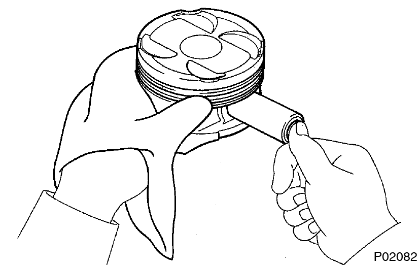
Coat the piston pin with engine oil and push it into the connecting rod with your thumb.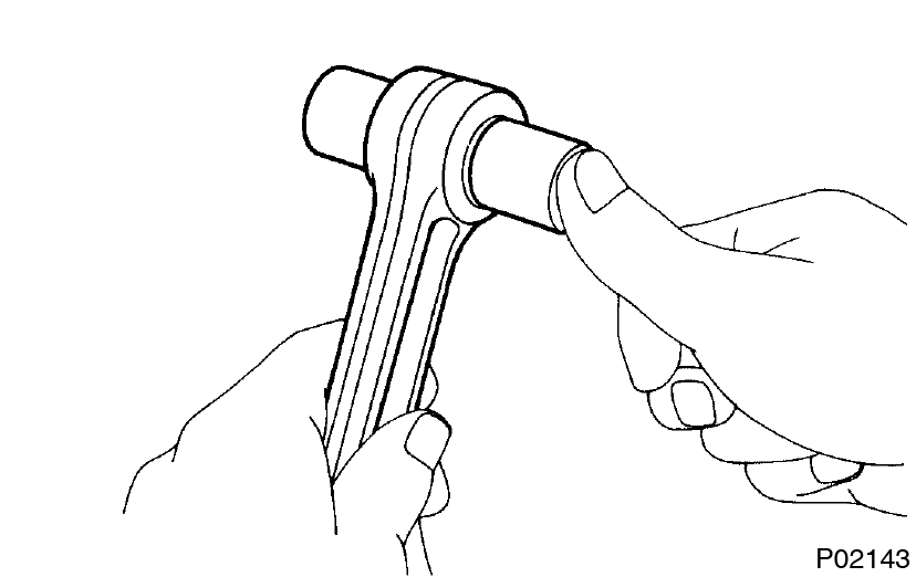
- Using a caliper gauge, measure the inside diameter of the connecting rod bushing.
- Inspect connecting ROD bolts
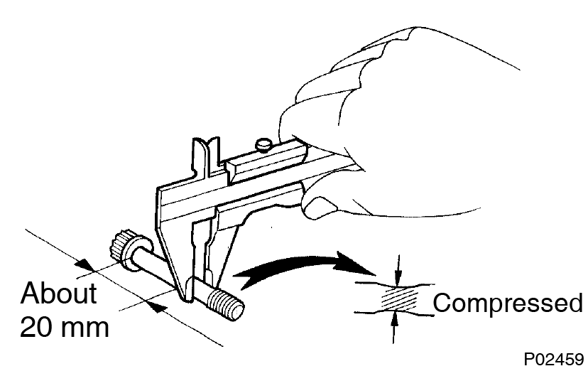 Using vernier calipers, measure the minimum diameter of the compressed bolt at the measuring point.
Standard diameter: 8.1 - 8.3 mm (0.319 - 0.327 in.)
Minimum diameter: 8.0 mm (0.315 in.)
If the diameter is less than minimum, replace the connecting rod bolt. - Inspect crankshaft for runout
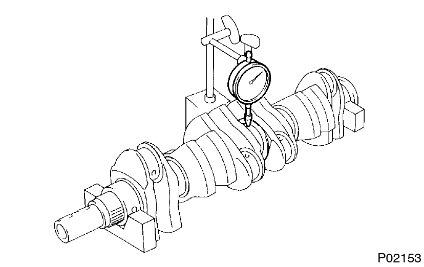
- Place the crankshaft on V-blocks.
- Using a dial indicator, measure the circle runout at the center journal.
Maximum circle runout: 0.06 mm (0.0024 in.)
If the circle runout is greater than maximum, replace the crankshaft.
- Inspect main journals and crank pins
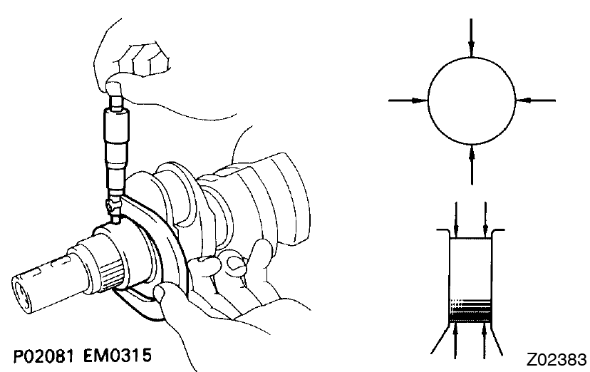
- Using a micrometer, measure the diameter of each main journal and crank pin.
Diameter:If the diameter is not as specified, check the oil clearance. (See page EM-71 )Item STD mm (in.) U/S 0.25 mm (in.) Main journal 61.984 - 62.000 (2.4403 - 2.4409) 61.745 - 61.755 (2.4309 - 2.4313) Crank pin 51.982 - 52.000 (2.0465 - 2.0472) 51.745 - 51.755 (0.0372 - 2.0376) - Check each main journal and crank pin for taper and outof-round as shown.
Maximum taper and out-of round:
0.02 mm (0.0008 in.)
If the taper or out-of-round is greater than maximum, grind or replace the crankshaft.
- Using a micrometer, measure the diameter of each main journal and crank pin.
- If necessary, grind and hone main journals and/or crank pins
- Grind and hone the main journals and/or crank pins to the finished undersized diameter (See procedure step 17).
- Install new main journal and/or crank pin undersized bearings.
This guide is based on the book edition Toyota (RM502U, 1997)