


- Introduction
- Maintenance
- Preparation
- Service specifications
- Diagnostics
- 2JZ-GE Engine
- 2JZ-GTE Engine
- 2JZ-GTE Turbocharging
- 2JZ-GE Emission control
- 2JZ-GTE Emission control
- 2JZ-GE SFI
- 2JZ-GTE SFI
- Cooling
- Lubrication
- Ignition system 2JZ-GE
- Ignition system 2JZ-GTE
- Starting system
- Charging system
- Clutch
- W58 manual transmission
- V160 manual transmission
- A340E 2JZ-GE automatic transmission
- A340E 2JZ-GTE automatic transmission
- Propeller shaft
- Suspension and axle
- Brake system
- Steering
- Supplemental restraint system
- Body electrical system
- Body
- Air conditioning system
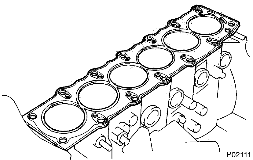
- Place cylinder head on cylinder block
- Place a new cylinder head gasket in position on the cylinder block. Be sure to install it correctly.
- Connect the heater hose to the heater union.
- Place the cylinder head in position on the cylinder head gasket.
- Place a new cylinder head gasket in position on the cylinder block.
- Install cylinder head bolts
- The cylinder head bolts are tightened in 2 progressive steps (steps (c) and (f)).
- If any of bolts break or deform, replace them.
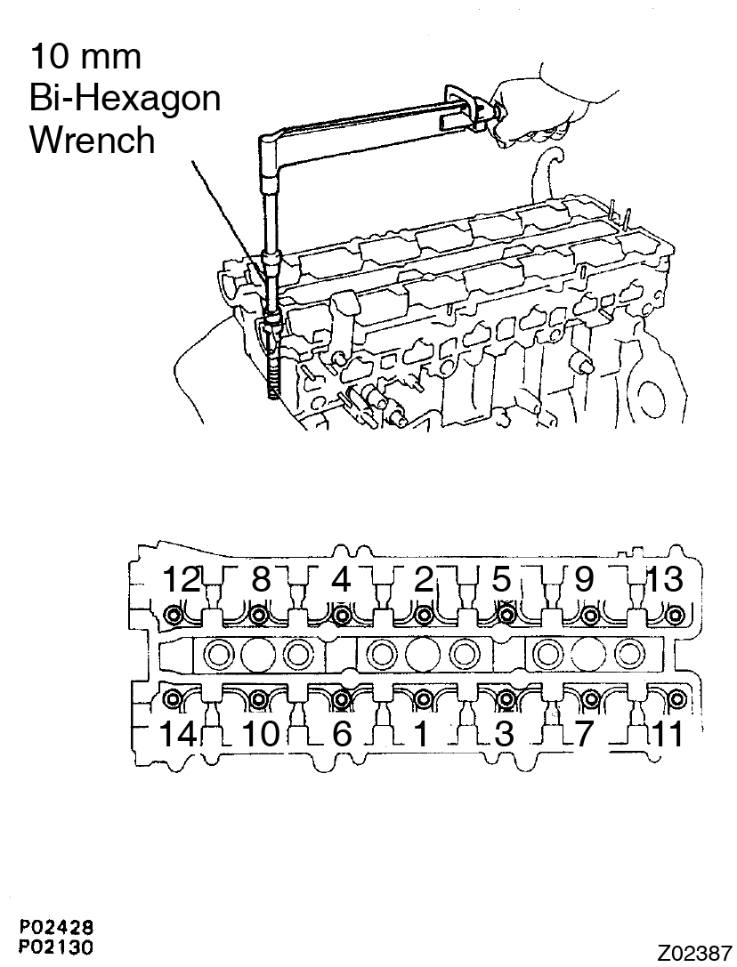
- Apply a light coat of engine oil on the threads and under the heads of the cylinder head bolts.
- Install the 14 plate washers to each cylinder head bolt.
- Using a 10 mm bi-hexagon wrench, uniformly tighten the cylinder head bolts, in several passes, in the sequence shown.
Torque: 34 N·m (350 kgf·cm, 25 ft·lbf)
If any of the bolts do not meet the torque specification, replace the bolt. - Mark the front of the cylinder head bolt head with paint.
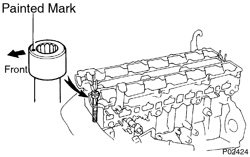
- Retighten the cylinder head bolts 90° in the numerical order shown.
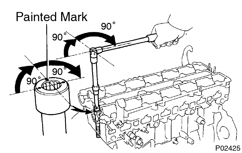
- Retighten cylinder head bolts by an additional 90° shown.
- Check that the painted mark is now turned to the rear.
- Install camshafts
- Apply engine oil to the thrust portion of the camshaft.
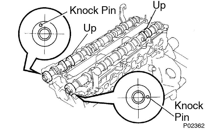
- Place the camshaft on the cylinder head with the cam lobe facing up as shown.
- Place the (Nos. 3, 7 journal) No.2 camshaft bearing caps in their proper location.
- Apply a light coat of engine oil on the threads and under the heads of the bearing cap bolts.
- Temporarily tighten these bearing cap bolts uniformly and alternately, in several passes, until the bearing caps are snug with the cylinder head.
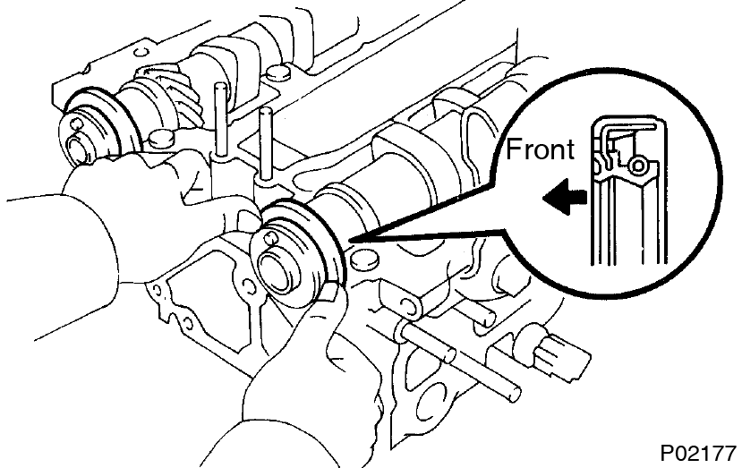
- Apply MP grease to a new camshaft oil seal lip.
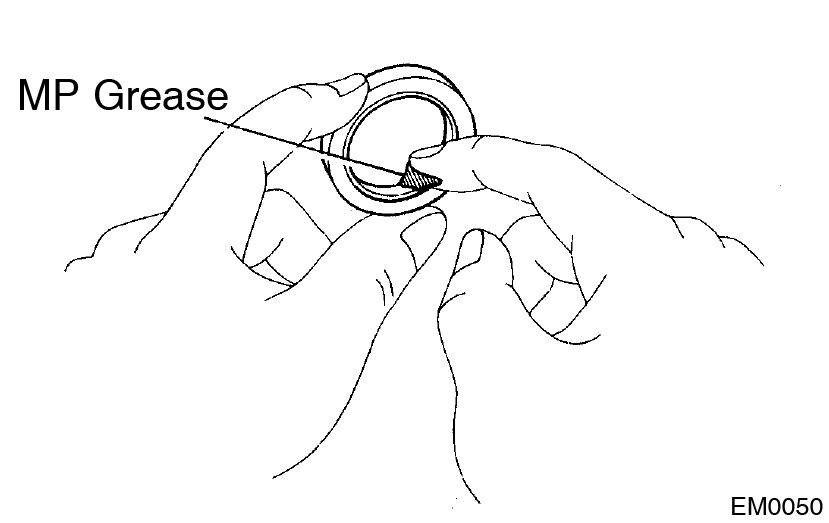
- Install the 2 oil seals to the camshafts.
- Clean the installed surfaces of the Nos.1, 3 camshaft bearing caps and cylinder head with cleaner.
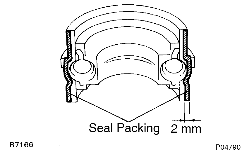
- Apply seal packing to the bearing caps as shown.
Seal packing:
Part No. 08826-00080 or equivalent - Install the No.1 , No.2, No.4, No.5 and No.6 bearing caps in their proper locations.
- Apply a light coat of engine oil on the threads and under the heads of the bearing cap bolts.
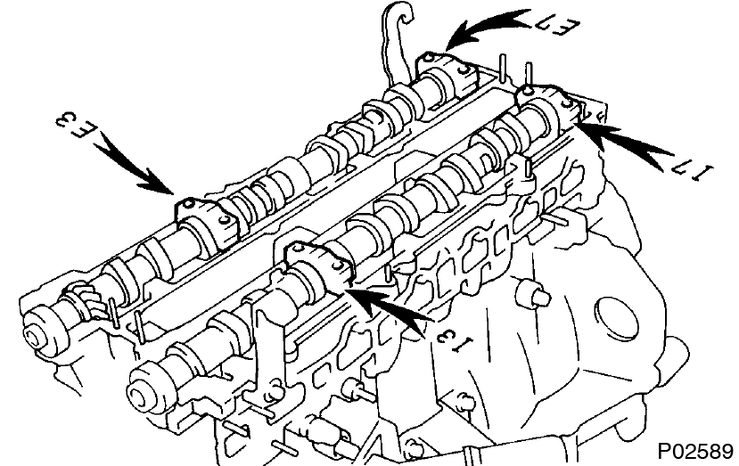
- Install and uniformly tighten the 14 bearing cap bolts on one side, in several passes, in the sequence shown.
Torque: 20 N·m (200 kgf·cm, 15 ft·lbf)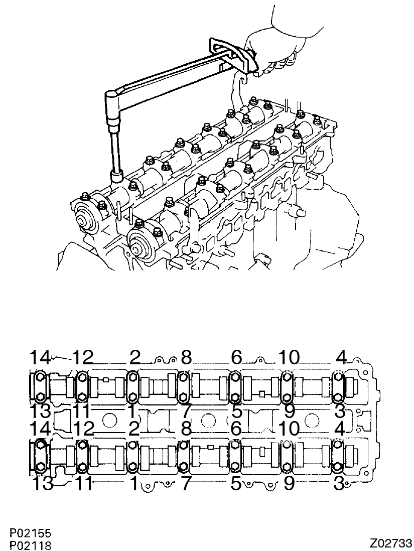
- Using a 5 mm hexagon wrench, the 2 No.3 camshaft bearing cap bolts.
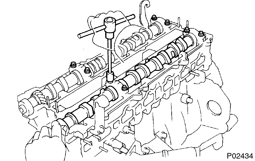
Torque: 5.0 N·m (50 kgf·cm, 44 in.·lbf) - Using SST, push the 2 oil seals in as far as they can go.
SST 09316-6001 1 (09316-00011, 09316-00051)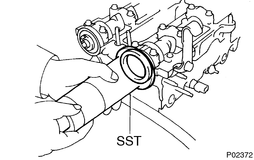
- Rotate the camshaft with a wrench at the hexagon position, bring the forward straight pin up.
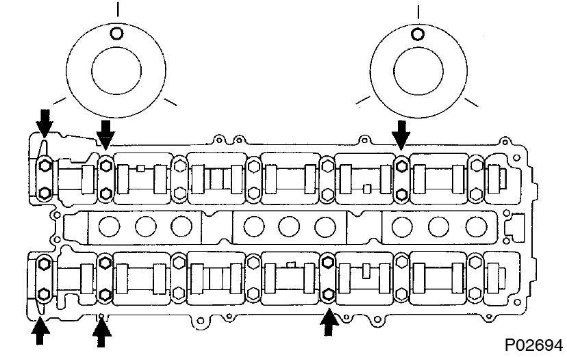
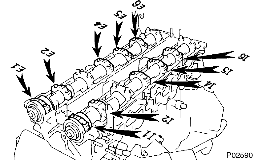
- Loosen the 12 bearing cap bolts as shown, until they can be turned by hand; retighten in several passes. Torque: 20 N·m (200 kgf·cm, 15 ft·lbf)
- Turn the camshaft 1/3 of a revolution.
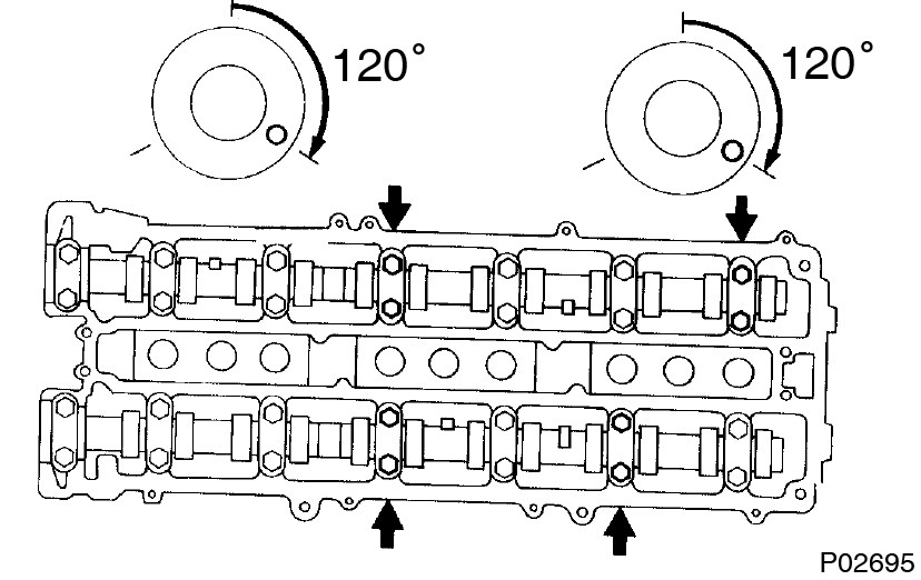
- Loosen the 8 bearing cap bolts as shown, until they can be turned by hand; retighten in several passes.
Torque: 20 N·m (200 kgf·cm, 15 ft·lbf) - Turn the camshaft a further 1/3 of a revolution.
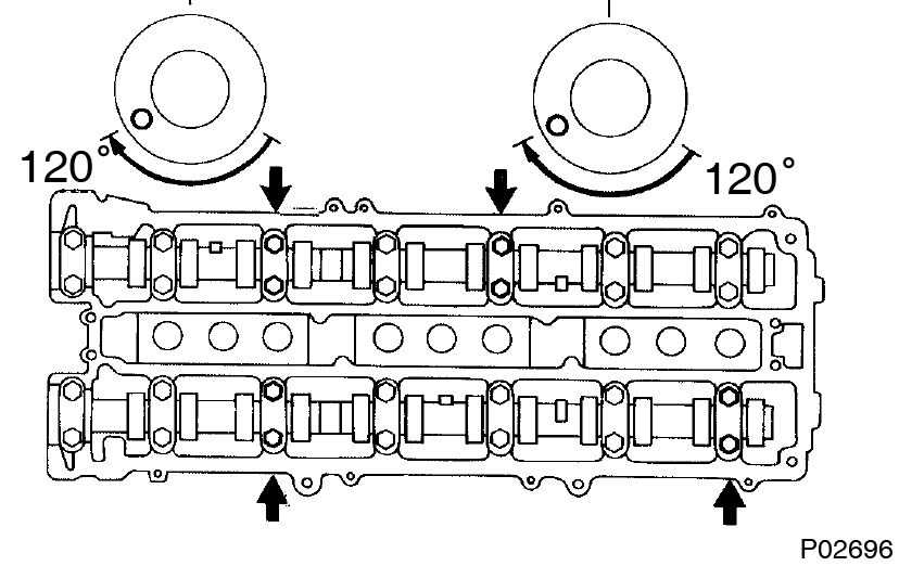
- Loosen the 8 bearing cap bolts as shown, until they can be turned by hand; retighten in several passes.
Torque: 20 N·m (200 kgf·cm, 15 ft·lbf)
- Apply engine oil to the thrust portion of the camshaft.
- Check and adjust valve clearance (See page EM-4 )
- Install No.4 timing belt cover
Install the timing belt cover with 4 bolts.
Torque: 8.0 N·m (80 kgf·cm, 71 in.·lbf)
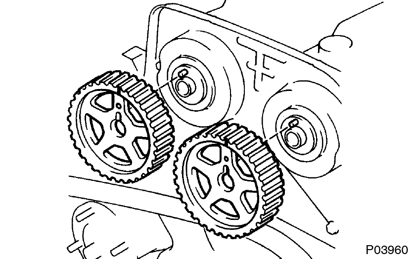
- Install camshaft timing pulleys
- Install the exhaust camshaft timing pulley.
- Align the camshaft knock pin with the groove in the pulley, and slide on the pulley.
- Temporarily install the timing pulley bolt.
- Hold the hexagon portion of the camshaft with a wrench, and tighten the timing pulley bolt.
Torque: 79 N·m (810 kgf·cm, 59 ft·lbf)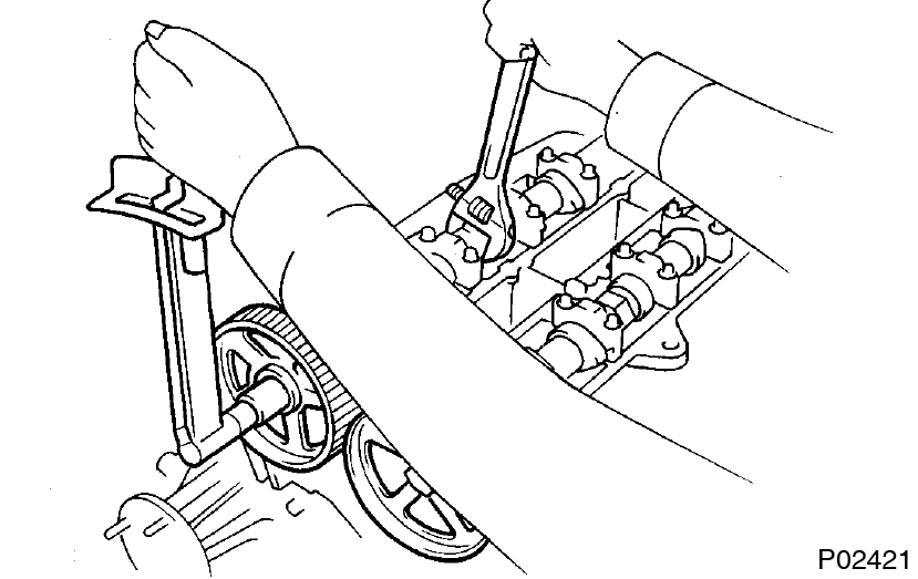
- Align the camshaft knock pin with the groove in the pulley, and slide on the pulley.
- Install the exhaust camshaft timing pulley.
- Install No.3, No.1 and No.2 cylinder head covers

- Remove the any old packing (FIPG) material.
- Apply seal packing to the cylinder head as shown in the illustration.
Seal packing: Part No. 08826-00080 or equivalent - Install the gaskets to the No.1 and No.2 cylinder head covers.
- Install the No.1 cylinder head covers with the 4 bolts.
Torque: 8.3 N·m (85 kgf·cm, 74 in.·lbf) - Install the No.2 cylinder head covers with the 4 bolts.
Torque: 8.3 N·m (85 kgf·cm, 74 in.·lbf) - Install the No.3 cylinder head covers with the 4 bolts and 4 nuts.
Torque: 8.3 N·m (85 kgf·cm, 74 in.·lbf) - Install the PCV valve.
- Install intake manifold assembly
Install the new gasket, the intake manifold and delivery pipe assembly with the 6 bolts and 2 nuts.
Torque: 27 N·m (280 kgf·cm, 20 ft·lbf)
- Install fuel inlet pipe
- Connect the fuel inlet pipe with 2 new gaskets and the union bolt.
Torque: 42 N·m (420 kgf·cm, 30 ft·lbf)
- Install the clam bolt to the intake manifold.
- Connect the fuel inlet pipe with 2 new gaskets and the union bolt.
- Install fuel pressure pulsation damper (See page SF-30)
- Install intake manifold stay
Torque: 39 N·m (400 kgf·cm, 29 ft·lbf) - Install water outlet with water bypass hose
Torque: 21 N·m (210 kgf·cm, 15 ft·lbf) - Connect engine wire
- Install the engine wire protector to the intake manifold with the 3 nuts.
- Connect these connectors:
- 6 injector connectors The No.1, No.3 and No.5 injector connectors are dark gray, and the No.2, No.4 and No.6 injector connectors are gray.
- ECT sensor connector
- ECT sender gauge connector
- A/C compressor connector
- . Oil level sensor connector
- Oil pressure switch connector
- 2 knock sensor connectors
- 6 injector connectors
- Install the wire clamp to the fuel return pipe.
- Install the 2 ground straps to the intake manifold with the bolts.
- Connect these connectors:
- Crankshaft position sensor connector
- Heated oxygen sensor (bank 1 sensor 1) connector
- Connect the wire clamp to the bracket.
- Install timing belt (See page EM-19)
- Install spark plugs
- Install distributor and high-tension cords assembly (See page IG-18)
- Connect high-tension cords to cylinder head covers (See page IG-10)
- Install No.3 timing belt cover
- Install cylinder head rear cover
- Install air intake chamber

- Install a new gasket and the intake chamber with the 5 bolts and nut.
Torque: 27 N·m (280 kgf·cm, 20 ft·lbf) - Install the bolt holding the engine wire protector to the air intake chamber.
- Connect these hoses:
- Vacuum hose to brake booster union
- EVAP hose to No.2 vacuum pipe
- Install a new gasket and the intake chamber with the 5 bolts and nut.
- Install DLC1 bracket and VSV assembly
- Install vacuum control valve set
Torque: 21 N·m (210 kgf·cm, 15 ft·lbf) - Install No.2 vacuum pipe and VSV assembly
Torque: 27 N·m (280 kgf·cm, 20 ft·lbf) - Connect EGR GAS temperature sensor connector
- Install oil dipstick and guide for engine (See page LU-16 )
- Install oil dipstick and gauge for transmission (See page EM-64)
- Install air intake chamber stays
 The No.1 stay is marked with ”F”, and No.2 stay is marked with ”R”.
- Install the No.1 stay with the bolt and nut.
Torque: 18 N·m (185 kgf·cm, 13 ft·lbf) - Install the No.2 stay with the bolt and nut.
Torque: 18 N·m (185 kgf·cm, 13 ft·lbf)
- Install the No.1 stay with the bolt and nut.
- Install throttle body and intake air connector assembly (See page SF-25)
- Install engine wire bracket
- Connect fuel return hose
- Install PS pump
- Install the pump rear stay with the 2 bolts.
Torque: 39 N·m (400 kgf·cm, 29 ft·lbf) - Install the vane pump with the 2 bolts.
Torque: 58 N·m (590 kgf·cm, 43 ft·lbf) - Connect these hoses:
- PS air hose to No.4 timing belt cover
- PS air hose to air intake chamber
- Install the pump rear stay with the 2 bolts.
- Install No.1 water bypass pipe and water bypass outlet (See page CO-1 1)
- Install exhaust manifolds
- Install a new gasket and the exhaust manifold with 4 the nuts. Install the No.1 and No.2 exhaust manifolds.
Torque: 39 N·m (400 kgf·cm, 29 ft·lbf) - Connect the 2 heated oxygen sensor connectors.
- Install a new gasket and the exhaust manifold with 4 the nuts. Install the No.1 and No.2 exhaust manifolds.
- Install No.2 front exhaust pipe (See page EM-64)
- Install drive belt
Install the drive belt by turning the drive belt tensioner clockwise. - Install air cleaner, MAF meter and intake air connector pipe assembly
- Install air cleaner dust
- Fill with engine coolant
- Start engine and check for leaks
- Check ignition timing (See page IG-18 )
- Install engine under cover
- Road test
Check for abnormal noise, shock, slippage, correct shift points and smooth operation. - Check engine coolant level
This guide is based on the book edition Toyota (RM502U, 1997)