


- Introduction
- Maintenance
- Preparation
- Service specifications
- Diagnostics
- 2JZ-GE Engine
- 2JZ-GTE Engine
- 2JZ-GTE Turbocharging
- 2JZ-GE Emission control
- 2JZ-GTE Emission control
- 2JZ-GE SFI
- 2JZ-GTE SFI
- Cooling
- Lubrication
- Ignition system 2JZ-GE
- Ignition system 2JZ-GTE
- Starting system
- Charging system
- Clutch
- W58 manual transmission
- V160 manual transmission
- A340E 2JZ-GE automatic transmission
- A340E 2JZ-GTE automatic transmission
- Propeller shaft
- Suspension and axle
- Brake system
- Steering
- Supplemental restraint system
- Body electrical system
- Body
- Air conditioning system

 <Reference>

Inspection procedure
See DTC P0401 for SYSTEM CHECK DRIVING PATTERN and WIRING DIAGRAM. Inspection procedure
Inspection procedure


Inspection procedure
Inspection procedure
| DTC | P0100 | Mass Air Flow Circuit Malfunction |
Circuit description
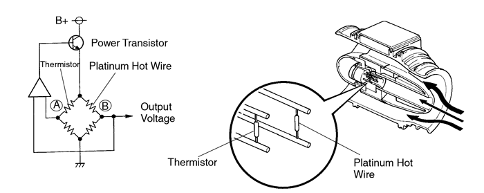
The mass air flow meter uses a platinum hot wire. The hot wire air flow meter consists of a platinum hot wire, thermistor and a control circuit installed in a plastic housing. The hot wire air flow meter works on the principle that the hot wire and thermistor located in the intake air bypass of the housing detect any changes in the intake air temperature.
The hot wire is maintained at the set temperature by controlling the current flow through the hot wire. This current flow is then measured as the output voltage of the air flow meter.
The circuit is constructed so that the platinum hot wire and thermistor provide a bridge circuit, with the power transistor controlled so that the potential of ”A” and ”B” remains equal to maintain the set temperature.

| DTC No. | DTC Detecting Condition | Trouble Area |
| P0100 | Open or short in mass air flow meter circuit with engine speed 4,000 rpm or less |
|
| Open or short in mass air flow meter circuit with engine speed 4,000 rpm or more (2 trip detection logic) |
If the ECM detects DTC ”P0100” it operates the fail safe function, keeping the ignition timing and injection volume constant and making it possible to drive the vehicle.
After confirming DTC P0100 use the OBD II scan tool or TOYOTA hand-held tester to confirm the mass air flow ration from ”CURRENT DATA”.
| Mass Air Flow Value (gm / sec.) | Malfunction |
| 0.0 |
|
| 271.0 or more | • VG- circuit open |
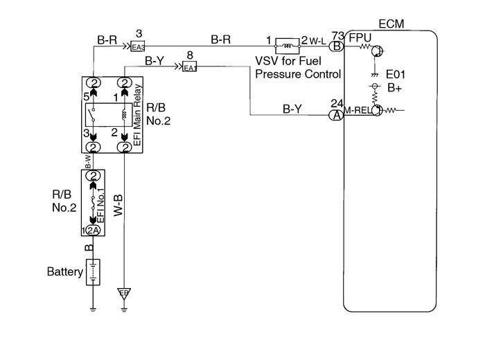
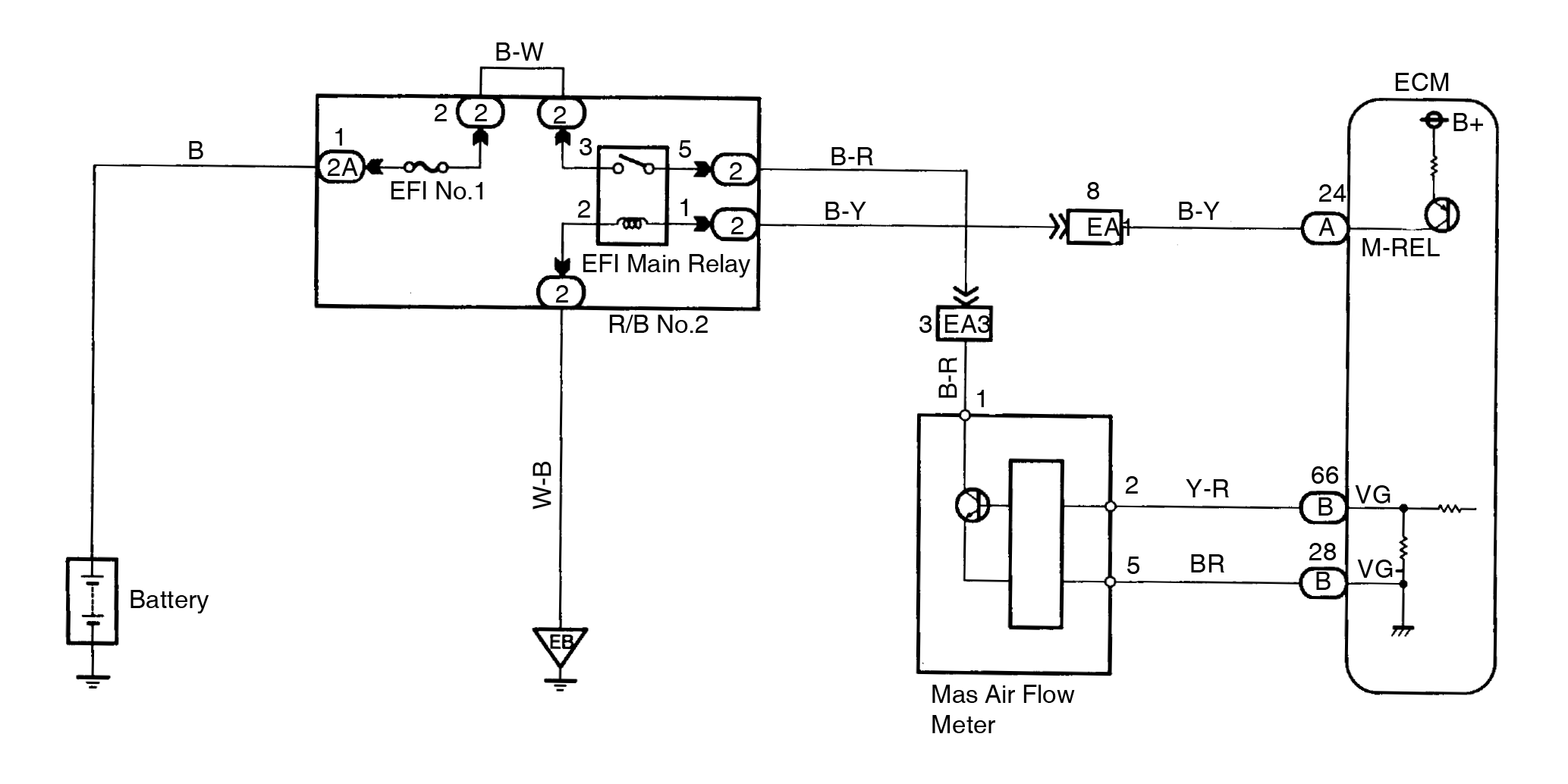
Wiring diagram
Inspection procedure
| 1 | Connect the OBD II scan tool or TOYOTA hand-held tester, and read value of mass air flow rate. | ||||||||
PREPARATION:
Read mass air flow rate on the OBD II scan tool or TOYOTA hand-held tester. RESULT:
| |||||||||
| Type I | Go to step 2. | ||||||||
| TypeII | Go to step 5. | ||||||||
| 2 | Check voltage of mass air flow meter power source. | ||||||||
 PREPARATION: PREPARATION:
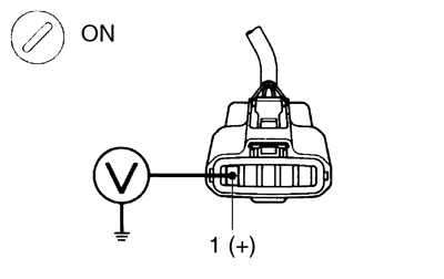
Measure voltage between terminal 1 of mass air flow meter connector and body ground. OK: Voltage: 9 - 14 V | |||||||||
| NG | Check for open in harness and connector between EFI main relay (Marking: EFI MAIN) and mass air flow meter (See page IN-28). | ||||||||
| OK | |||||||||
| 3 | Check voltage between terminal VG of ECM and body ground. | ||||||||
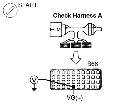 PREPARATION: PREPARATION:
Measure voltage between terminal VG of ECM and body ground while engine is idling, transmission is in park or neutral position and A/C switch is OFF. OK: Voltage: 1.1 - 1.5 V | |||||||||
| OK | Check and replace ECM (See page IN-28). | ||||||||
| NG | |||||||||
| 4 | Check for open and short in harness and connector between mass air flow meter and ECM (See page IN-28). | ||||||||
| NG | Repair or replace harness or connector | ||||||||
| OK | |||||||||
| Replace mass air flow meter. | |||||||||
| 5 | Check continuity between terminal VG- of ECM and body ground. | ||||||||
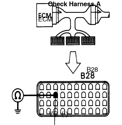 PREPARATION: PREPARATION: Connect Check Harness A (See pageDI-20). CHECK: Check continuity between terminal VG- of ECM and body ground. OK: Continuity (1 Ω or less) | |||||||||
| NG | Check and replace ECM (See page IN-28). | ||||||||
| OK | |||||||||
| 6 | Check for open in harness and connector between mass air flow meter and ECM (See page IN-28). | ||||||||
| NG | Repair or replace harness or connector. | ||||||||
| OK | |||||||||
| Replace mass air flow meter (See page SF-36). | |||||||||
| DTC | P0101 | Mass Air Flow Circuit Range / Performance Problem |
Circuit description
Refer to Mass Air Flow Circuit Malfunction on page DI-25 .
| DTC No. | DTC Detecting Condition | Trouble Area |
| P0101 | Conditions (a) and (b) continue with engine speed 1,000 rpm or less: (2 trip detection logic)
| • Mass air flow meter |
| Conditions (a) and (b) continue with engine speed 2,000 rpm or more: (2 trip detection logic)
|
Wiring diagram
Refer to page DI-25 or the WARNING DIAGRAM.
Inspection procedure
| 1 | Are there any other codes (besides DTC P0101) being output? | ||
| YES | Go to relevant DTC chart. | ||
| NO | |||
| Replace mass air flow meter (See page SF-36). | |||
| DTC | P0110 | Intake Air Temp. Circuit Malfunction |
Circuit description
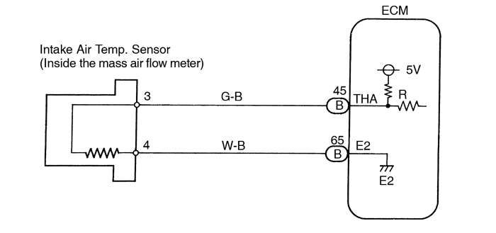
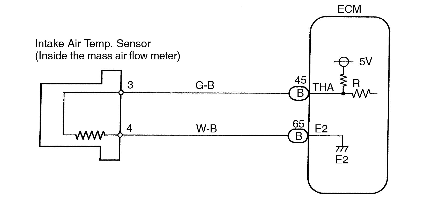
The intake air temperature sensor is built into the air flow meter and senses the intake air temperature.
A thermistor built in the sensor changes the resistance value according to the intake air temperature.
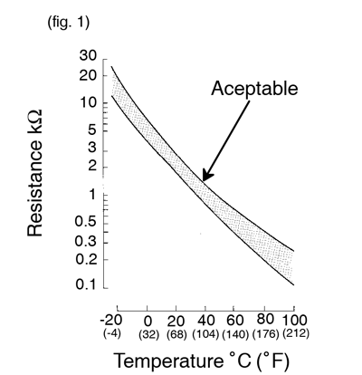
The lower the intake air temperature, the greater the thermistor resistance value, and the higher the intake air temperature, the lower the thermistor resistance value (See Fig. 1).
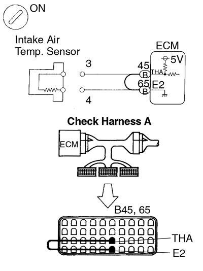
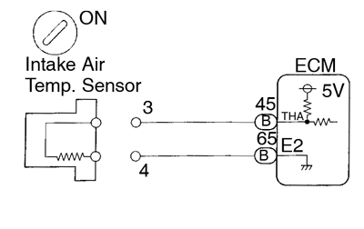
The intake air temperature sensor is connected to the ECM. The 5 V power source voltage in the ECM is applied to the intake air temperature sensor from the terminal THA via a resistor R.
That is , the resistor R and the intake air temperature sensor are connected in series. When the resistance value of the intake air temperature sensor changes in accordance with changes in the intake air temperature, the potential at terminal THA also changes. Based on this signal, the ECM increases the fuel injection volume to improve driveability during cold engine operation.
If the ECM detects the DTC ”P0110”, it operates the fail safe function in which the intake air temperature is assumed to be 20°C (68°F).
<Reference> | Intake Air Temp. °C (°F) | Resistance (kΩ) | Voltage (V) |
| -20 (-4) | 16.2 | 4.3 |
| 0 (32) | 5.9 | 3.4 |
| 20 (68) | 2.5 | 2.4 |
| 40 (104) | 1.1 | 1.4 |
| 60 (140) | 0.6 | 0.9 |
| 80 (176) | 0.3 | 0.5 |
| 100 (212) | 0.1 | 0.2 |
| DTC No.. | DTC Detecting Condition | Trouble Area |
| P0110 | Open or short in intake air temp. sensor circuit |
|
After confirming DTC P0110 use the OBD II scan tool or TOYOTA hand-held tester to confirm the intake air temperature from ”CURRENT DATA”.
| Temperature Displayed | Malfunction |
| - 40°C (- 40°F) | Open circuit |
| 140°C (284°F) or more | Short circuit |
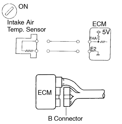
Wiring diagram
Inspection procedure
- If DTC ”P0110” (Intake Air Temp. Circuit Malfunction), ”P0105” (Engine Coolant Temp. Circuit Malfunction), ”P0120” (Throttle/Pedal Position Sensor/Switch ”A” Circuit Malfunction) are output simultaneously, E2 (sensor ground) may be open.
| 1 | Connect the OBD II scan tool or TOYOTA hand-held tester, and read value of intake air temperature. | ||
PREPARATION:
Read temperature value on the OBD II scan tool or TOYOTA hand-held tester. OK: Same as actual intake air temperature.
| |||
| NG | - 40°C (- 40°F) ............... Go to step 2. 140°C (284°F) or more .. Go to step 4. | ||
| OK | |||
| Check for intermittent problems (See page DI-3). | |||
| 2 | Check for open in harness or ECM. | ||
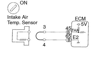 PREPARATION: PREPARATION:
Read temperature value on the OBD II scan tool or TOYOTA hand-held tester. OK: Temperature value: 140°C (284°F) or more | |||
| OK | Confirm good connection at sensor. If OK, replace mass air flow meter (See page SF-36). | ||
| NG | |||
| 3 | Check for open in harness or ECM. | ||
 PREPARATION: PREPARATION:
Read temperature value on the OBD II scan tool or TOYOTA hand-held tester. OK: Temperature value: 140°C (284°F) or more | |||
| OK | Open in harness between terminals E2 or THA, repair or replace harness. | ||
| NG | |||
| Confirm good connection at ECM. If OK, replace ECM. | |||
| 4 | Check for short in harness and ECM. | ||
 PREPARATION: PREPARATION:
Read temperature value on the OBD II scan tool or TOYOTA hand-held tester. OK: Temperature value: - 40°C (- 40°F). | |||
| OK | Replace mass air flow meter. (See page SF-36). | ||
| NG | |||
| 5 | Check for short in harness or ECM. | ||
 PREPARATION: PREPARATION:
Read temperature value on the OBD II scan tool or TOYOTA hand-held tester. OK: Temperature value: - 40°C (- 40°F) | |||
| OK | Repair or replace harness or connector | ||
| NG | |||
| Check and replace ECM (See page IN-28). | |||
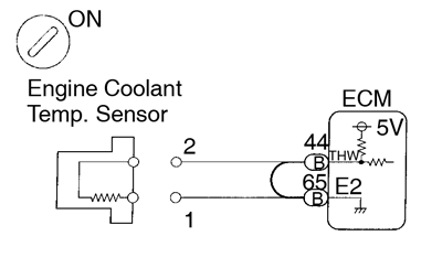
| DTC | P0115 | Engine Coolant Temp. Circuit Malfunction |
Circuit description
A thermistor built into the engine coolant temperature sensor changes the resistance value according to the engine coolant temperature.
The structure of the sensor and connection to the ECM is the same as in the intake air temperature circuit malfunction shown on page DI-30 .
If the ECM detects the DTC P0115, it operates the fail safe function in which the engine coolant temperature is assumed to be 80°C (176°F)
| DTC No. | DTC Detecting Condition | Trouble Area |
| P0115 | Open or short in engine coolant temp. sensor circuit. |
|
After confirming DTC P0115 use the OBD II scan tool or TOYOTA hand-held tester to confirm the engine coolant temperature from ”CURRENT DATA”.
| Temperature Displayed | Malfunction |
| - 40°C (- 40°F) | Open circuit |
| 140°C (284°F) or more | Short circuit |
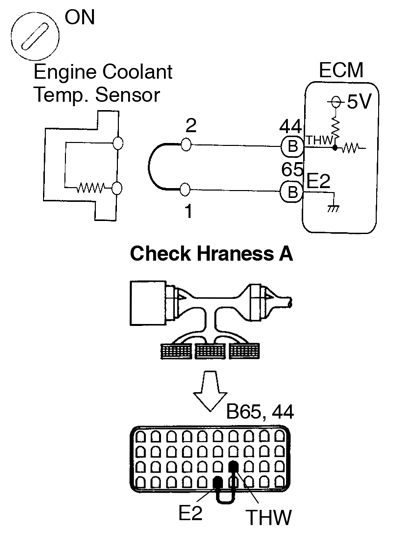
Wiring diagram
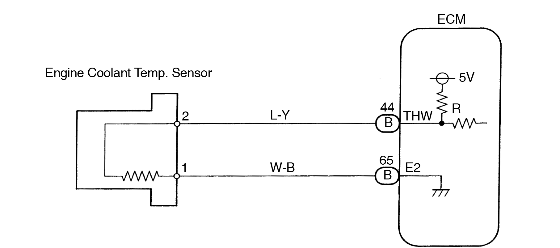
Inspection procedure
- If DTC ”P0110” (Intake Air Temp. Circuit Malfunction), ”P0115” (Engine Coolant Temp. Circuit Malfunction), ”P0120” (Throttle/Pedal Position Sensor/Switch ”A” Circuit Malfunction) are output simultaneously, E2 (sensor ground) may be open.
| 1 | Connect the OBD II scan tool or TOYOTA hand-held tester, and read value of engine coolant temperature. | ||
PREPARATION:
Read temperature value on the OBD II scan tool or TOYOTA hand-held tester. OK: Same as actual engine coolant temperature.
| |||
| NG | - 40°C ( - 40°F) ............... Go to step 2. 140°C (284°F) or more .... Go to step 4. | ||
| OK | |||
| Check for intermittent problems (See page DI-3). | |||
| 2 | Check for open in harness or ECM. | ||
 PREPARATION: PREPARATION:
Read temperature value on the OBD II scan tool or TOYOTA hand-held tester. OK: Temperature value: 140°C (284°F) or more | |||
| OK | Confirm good connection at sensor. If OK, replace engine coolant temp. sensor. | ||
| NG | |||
| 3 | Check for open in harness or ECM. | ||
 PREPARATION: PREPARATION:
Read temperature value on the OBD II scan tool or TOYOTA hand-held tester. OK: Temperature value: 140°C (284°F) or more | |||
| OK | Open in harness between terminals E2 or THW, repair or replace harness. | ||
| NG | |||
| Confirm good connection at ECM. If OK, replace ECM. | |||
| 4 | Check for short in harness and ECM. | ||
PREPARATION:
Read temperature value on the OBD II scan tool or TOYOTA hand-held tester. OK: Temperature value: - 40°C (- 40°F) | |||
| OK | Replace engine coolant temp. sensor (See page SF-65). | ||
| NG | |||
| 5 | Check for short in harness or ECM. | ||
PREPARATION:
Read temperature value on the OBD II scan tool or TOYOTA hand-held tester. OK: Temperature value: - 40°C (- 40°F) | |||
| OK | Repair or replace harness or connector. | ||
| NG | |||
| Check and replace ECM (See page IN-28). | |||
| DTC | P0116 | Engine Coolant Temp. Circuit Range/ Performance Problem |
Circuit description
Refer to Engine Coolant Temp. Circuit Malfunction on page DI-34 .
| DTC No. | DTC Detecting Condition | Trouble Area |
| P0116 | When the engine starts, the engine coolant temp. is -7°C (20°F) or less. And, 20 min. or more after the engine starts, the engine coolant temp. sensor value is less than 22.4°C (72.3°F) (2 trip detection logic) |
|
| When the engine starts, the engine coolant temp. is between -7°C (20°F) and 10°C (50°F). And, 5 min. or more after the engine starts, the engine coolant temp. sensor value is less than 22.4°C (72.3°F) (2 trip detection logic) | ||
| When the engine starts, the engine coolant temp. is between 10°C (50°F) and 20°C (68°F). And, 2 min. or more after the engine starts, the engine coolant temp. sensor value is less than 22.4°C (72.3°F) (2 trip detection logic) | ||
| When the engine starts, the engine coolant temp. is 20°C (68°F) or more. And, 2 min. or more after the engine starts, the engine coolant temp. sensor value is less than 42°C (107.6°F) (2 trip detection logic) |
Inspection procedure
If DTC ”P0115” (Engine Coolant Temp. Circuit Malfunction) and ”P0116” (Engine Coolant Temp. Circuit Range/Performance) are output simultaneously, engine coolant temp. sensor circuit may be open. Perform troubleshooting of DTC P0115 first.
| 1 | Are there any other codes (besides DTC P0116) being output? | ||
| YES | Go to relevant DTC chart. | ||
| NO | |||
| 2 | Check thermostat (See page CO-15). | ||
| NG | Replace thermostat. | ||
| OK | |||
| Replace engine coolant temp. sensor. (See page CO-15) | |||
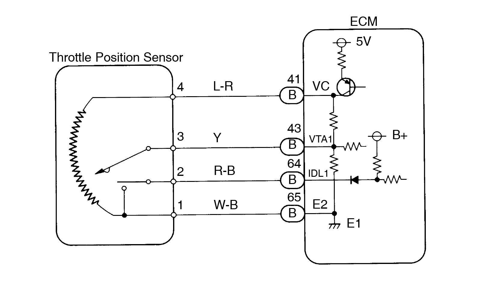
| DTC | P0120 | Throttle / Pedal Position Sensor / Switch ”A” Circuit Malfunction |
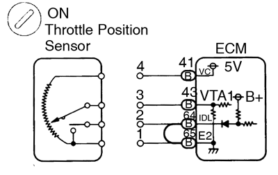
Circuit description
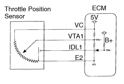
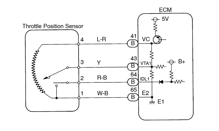
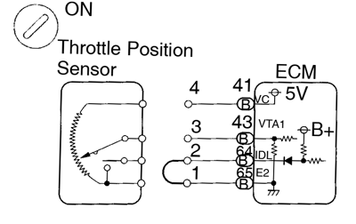
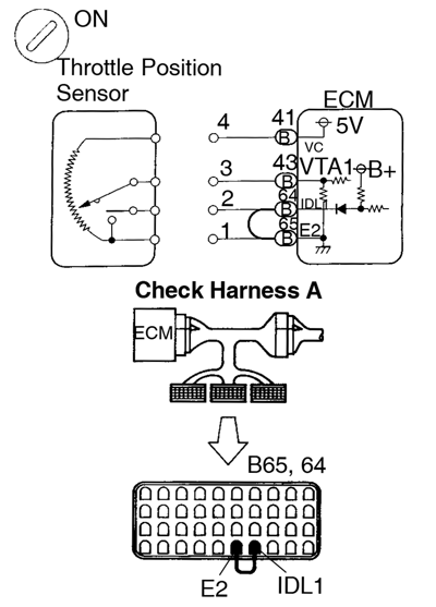
The throttle position sensor is mounted in the throttle body and detects the throttle valve opening angle. When the throttle valve is fully closed, the IDL1 contacts in the throttle position sensor are on, so the voltage at the terminal IDL1 of the ECM becomes 0 V. At this time, a voltage of approximately 0.7 V is applied to terminal VTA1 of the ECM. When the throttle valve is opened, the IDL1 contacts go off and thus the power source voltage of approximately 12 V in the ECM is applied to the terminal IDL1 of the ECM. The voltage applied to the terminal VTA1 of the ECM increases in proportion to the opening angle of the throttle valve and becomes approximately 3.2 ∼ 4.9 V when the throttle valve is fully opened. The ECM judges the vehicle driving conditions from these signals input from terminals VTA1 and IDL1, and uses them as one of the conditions for deciding the air-fuel ratio correction, power increases correction and fuel-cut control etc.
| DTC No.. | DTC Detecting Condition | Trouble Area |
| P0120 | Condition (a) or (b) continues:
|
|
- If there is open circuit in IDL line, DTC P0120 does not indicate.
- After confirming DTC P0120 use the OBD II scan tool or TOYOTA hand-held tester to confirm the throttle valve opening percentage and closed throttle position switch condition.
| Throttle valve opening position expressed as percentage | Trouble Area | |
| Throttle valve fully closed | Throttle valve fully open | |
| 0 % | 0 % | VC line open VTA1 line open or short |
| Approx. 100 % | Approx. 100 % | E2 line open |
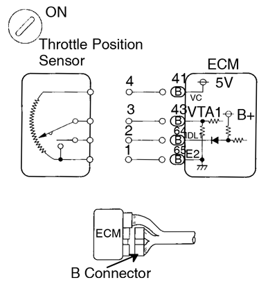
Wiring diagram
Inspection procedure
If DTC ”P0110” ’Intake Air Temp. Circuit Malfunction). ”P0115” (Engine Coolant Temp. Circuit Malfunction), ”P0120” (Throttle/Pedal Position Sensor/Switch ”A” Circuit Malfunction) are output simultaneously, E2 (sensor ground) may be open.
| 1 | Connect the OBD II scan tool or TOYOTA hand-held tester and read the throttle valve opening percentage. | ||||||||||||||
PREPARATION:
Read the throttle valve opening percentage.  OK: OK:
| |||||||||||||||
| OK | Check for intermittent problems (See page DI-3). | ||||||||||||||
| NG | |||||||||||||||
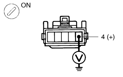
| 2 | Check voltage between terminal 4 of wire harness side connector and body ground. | ||||||||||||||
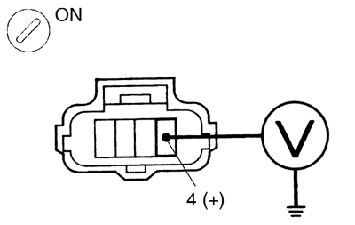 PREPARATION: PREPARATION:
Measure voltage between terminal 4 of wire harness side connector and body ground. OK: Voltage: 4.5 - 5.5 V | |||||||||||||||
| NG | Go to step 5. | ||||||||||||||
| OK | |||||||||||||||
| 3 | Check throttle position sensor. | ||||||||||||||
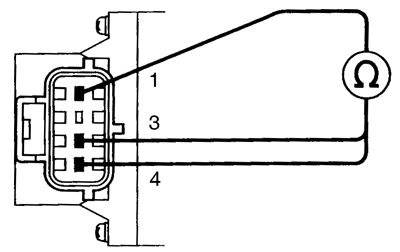 PREPARATION: PREPARATION: Disconnect the throttle position sensor connector. CHECK: Measure resistance between terminals 4, 3 and 1 of throttle position sensor. OK:
| |||||||||||||||
| NG | Replace throttle position sensor (See page SF-42). | ||||||||||||||
| OK | |||||||||||||||
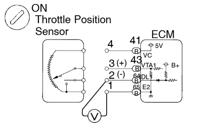
| 4 | Check voltage between terminals VTA1 and E2 of ECM. | ||||||||||||||
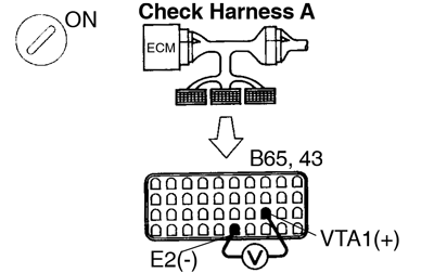 PREPARATION: PREPARATION:
Measure voltage between terminals VTA1 and E2 of ECM. OK:
| |||||||||||||||
| NG | Check for open and short in harness and connector between ECM and throttle position sensor (VTA line) (See page IN-28). | ||||||||||||||
| OK | |||||||||||||||
| Check and replace ECM (See page IN-28). | |||||||||||||||
| 5 | Check voltage between terminals VC and E2 of ECM. | ||||||||||||||
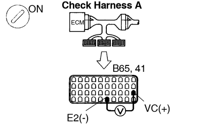 PREPARATION: PREPARATION:
Measure voltage between terminals VC and E2 of ECM connector. OK: Voltage 4.5 - 5.5 V | |||||||||||||||
| NG | Check and replace ECM (See page IN-28). | ||||||||||||||
| OK | |||||||||||||||
| Check for open in harness and connector between ECM and sensor (VC line) (See page IN-28). | |||||||||||||||
| DTC | P0121 | Throttle/Pedal Position Sensor/Switch ”A” Circuit Range/Performance Problem |
Circuit description
Refer to Throttle/Pedal PositionSensor/Switch ”A” circuit malfunction on page DI-40.
| DTC No. | DTC Detecting Condition | Trouble Area |
| P0121 | After the vehicle speed has been exceeded 30 km/h (19 mph) even once, the output value of the throttle position sensor is out of the applicable range while the vehicle speed between 30 km/h (19 mph) and 0 km/h (0 mph) |
|
Inspection procedure
| 1 | Are there any other codes(besides DTC P0121) being output? | ||
| YES | Go to relevant DTC chart. | ||
| NO | |||
| Replacethrottle position sensor (See page SF-42). | |||
| DTC | P0125 | Insufficient Coolant Temp. for Closed Loop Fuel Control |
Circuit description
To obtain a highpurification rate for the CO, HC and NOx components of the exhaust gas, a three-way cata- lytic converter is used,but for the most efficient use of the three-way catalytic converter, the air-fuel ratio must be precisely controlledso that it is always close to the stoichiometric air-fuel ratio.
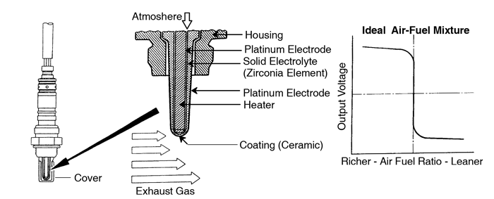
The oxygen sensor has thecharacteristic whereby its output voltage changes suddenly in the vicinity of the stoichiometric air-fuel ratio.This characteristic is used to detect the oxygen concentration in the exhaust gas and provide feedback to thecomputer for control of the air-fuel ratio.
When the air-fuel ratio becomesLEAN, the oxygen concentration in the exhaust increases and the oxygen sensor informs the ECM of the LEAN condition(small electromotive force: 0 V).
When the air-fuel ratio is RICHERthan the stoichiometric air-fuel ratio the oxygen concentration in the exhaust gas is reduced and the oxygensensor informs the ECM of the RICH condition (large electromotive force: 1 V).
The ECM judges by the electromotiveforce from the oxygen sensor whether the air-fuel ratio is RICH or LEAN and controls the injection time accordingly.However, if malfunction of the oxygen sensor causes out- put of abnormal electromotive force, the ECM is unable toperform accurate air-fuel ratio control.
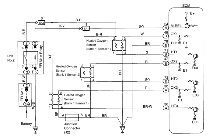
The heated oxygen sensors include a heater which heats the Zirconia element. The heater is controlled by the ECM. When the intake air volume is low (the temperature of the exhaust gas is low) current flows to the heater to heat the sensor for accurate oxygen concentration detection.

| DTC No. | DTC Detecting Condition | Trouble Area |
| P0125 | After the engine is warmed up, heated oxygen sensor output does not indicate RICH even once when conditions (a), (b) and (c) continue for at least 2 min.:
|
|
After confirming DTC P0125 use the OBD II scan tool or TOYOTA hand-held tester to confirm voltage output of heated oxygen sensor from”CURRENT DATA”.
If voltage output of heated oxygensensor is 0 V, heated oxygen sensor circuit may be open or short.
If voltage output of heated oxygensensor is 0 V, heated oxygen sensor circuit may be open or short.
Wiring diagram

Inspection procedure
| 1 | Connect the OBDII scan tool or TOYOTA hand-held tester and read value for voltage output of heated oxygen sensor. | ||
PREPARATION:
Read voltage outputof heated oxygen sensor (bank 1, 2 sensor 1) when engine is suddenly raced. Perform quick racing to 4,000 rpm 3 times using accelerator pedal. OK: Both heated oxygen sensors ((bank 1 sensor 1) (bank 2 sensor 1)) output a RICH signal (0.45 V or more) at least once. | |||
| OK | Check and replace ECM (See page IN-28). | ||
| NG | |||
| 2 | Check for open and short in harness and connector between ECM and heated oxygen sensor (See page IN-28). | ||
| NG | Repair or replace harness or connector. | ||
| OK | |||
| Replace heated oxygen sensor (See page SF-70). | |||
| DTC | P0130 | Heated Oxygen Sensor Circuit Malfunction (Bank 1 Sensor 1) |
| DTC | P0150 | Heated Oxygen Sensor Circuit Malfunction (Bank 2 Sensor 1) |
Circuit description
Refer to Insufficient Coolant Temp. for Closed Loop Fuel Control on page DI-45.
| DTC No. | DTC Detecting Condition | Trouble Area |
| P0130 P0150 | Voltage output of heated oxygen sensor remains at 0.4 V or more, or 0.55 V or less, during idling after the engine is warmed up (2trip detection logic) |
|
- Bank 1 refers to the bank that includes cylinder No.1.
- Bank 2 refers to the bank that dose notinclude cylinder No.1.
- Sensor 1 refers to the sensor closer to the engine body.
Wiring diagram
Refer to page DI-45 for the WIRING DIAGRAM.
Confirmation driving patten

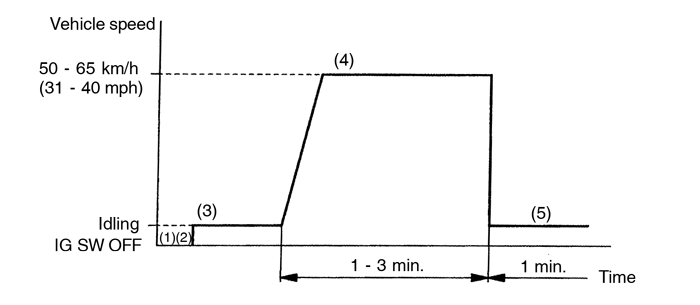
- Connect the TOYOTA hand-held tester to the DLC3.
- Switch the TOYOTA hand-held tester from normal mode to check mode (See page DI-3).
- Start the engine and warm it up with all accessory switches OFF.
- Drive the vehicle at 50 ~ 65 km/h (31 ~ 40 mph) for 1 ~ 3 min. to warm up the heated oxygen sensor.
- Let the engine idle for 1 min.
If a malfunction exists, the MIL willlight up during step (5).
If theconditions in this test are not strictly followed, detection of the malfunction will not be possible. If you do nothave a TOYOTA hand-held tester, turn the ignition switch OFF after performing steps (3) to (5), then performsteps (3) to (5) again.
Inspection procedure
| 1 | Check for openand short in harness and connector between ECM and heated oxygen sensor (See page IN-28). | ||||||||||||||
| NG | Repair or replace harness or connector. | ||||||||||||||
| OK | |||||||||||||||
| 2 | Check for heated oxygen sensor data. | ||||||||||||||
PREPARATION:
Read the heated oxygen sensor output voltage and short-term fuel trim. RESULT:
| |||||||||||||||
| 1, 2 | Check fuel trim system (See page DI-57). | ||||||||||||||
| 3 | |||||||||||||||
| 3 | Check the output voltage of heated oxygen sensor during idling. | ||||||||||||||
| PREPARATION: Warm up the heated oxygen sensor with the engine at 2,500 rpm for approx. 90 sec. CHECK: Use the OBD II scan tool or TOYOTA hand-held tester read the output voltage of the heated oxygen sensor during idling. OK: Heated oxygen sensor output voltage: Alternates repeatedly between less than 0.4 V and more than 0.55 V (See the following table). 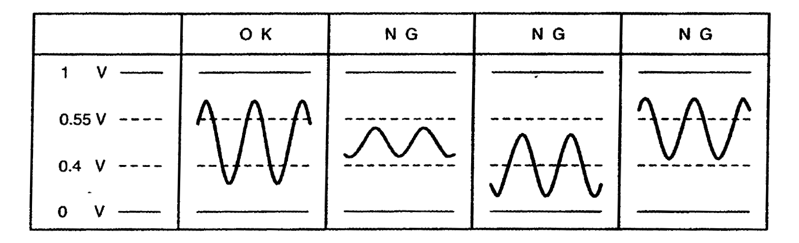 | |||||||||||||||
| OK | Perform confirmation driving pattern (See page DI-48). | ||||||||||||||
| NG | |||||||||||||||
| Replace heated oxygen sensor (See page SF-70). | |||||||||||||||
| DTC | P0133 | Heated Oxygen Sensor Circuit Slow Response (Bank 1 Sensor 1) |
| DTC | P0153 | Heated Oxygen Sensor Circuit Slow Response (Bank 2 Sensor 1) |
Circuit description
Refer to Insufficient Coolant Temp. for Closed Loop Fuel Control on page DI-45.
| DTC No. | DTC Detecting Condition | Trouble Area |
| P0133 P0153 | Response time for the heated oxygen sensor’s voltage output to change from rich to lean, or from lean to rich, is 1 sec. or more during idling after the engine is warmed up (2trip detection logic) |
|
- Bank 1 refers to the bank that includes cylinder No.1.
- Bank 2 refers to the bank that dose not includes cylinder No.1.
- Sensor 1 refers to the sensor closer to the engine body.
Inspection procedure
| 1 | Are there any other codes (besides DTC P0133, P0153) being output? | ||
| YES | Go to relevant DTC chart. | ||
| NO | |||
| Replace heated oxygen sensor (See page SF-70). | |||
| DTC | P0135 | Heated Oxygen Sensor Heater Circuit Malfunction (Bank 1 Sensor 1) |
| DTC | P0141 | Heated Oxygen Sensor Heater Circuit Malfunction (Bank 1 Sensor 2) |
| DTC | P0155 | Heated Oxygen Sensor Heater Circuit Malfunction (Bank 2 Sensor 1) |
Circuit description
Refer to Insufficient Coolant Temp. for Closed Loop Fuel Control on page DI-45.
| DTC No. | DTC Detecting Condition | Trouble Area |
| P0135 P0141 P0155 | When the heater operates, heater current exceeds 2 A (2 trip detection logic) |
|
| Heater current of 0.20 A or less when the heater operates (2 trip detection logic) |
- Bank 1 refers to the bank that includes cylinder No.1.
- Bank 2 refers to the bank that dose not includes cylinder No.1.
- Sensor 1 refers to the sensor closer to the engine body.
- Sensor 2 refers to the sensor farther away from the engine body.
Wiring diagram
Refer to page DI-45 for the WIRING DIAGRAM.
Inspection procedure
| 1 | Check voltage between terminals HT1, HT2, HT3 of ECM connector and body ground. | ||
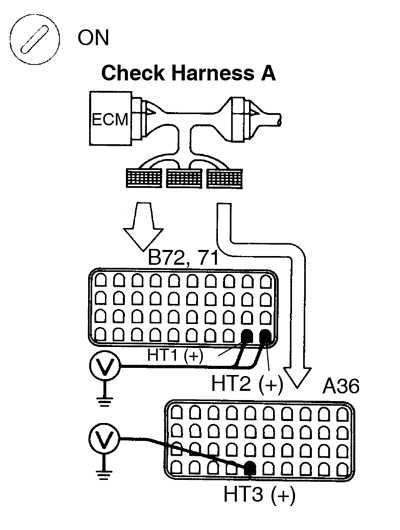 PREPARATION: PREPARATION:
Measure voltage between terminals HT1, HT2, HT3 of ECM connector and body ground.
Voltage: 9 - 14 V | |||
| OK | Check and replace ECM (See page IN-28). | ||
| NG | |||
| 2 | Check resistance of heated oxygen sensor heater (See page SF-72). | ||
| NG | Replace heated oxygen sensor (See page SF-70). | ||
| OK | |||
| Check and repair harness or connector between EFI main relay (Making: EFI MAIN) and heated oxygen sensor and ECM. | |||
| DTC | P0136 | Heated Oxygen Sensor Circuit Malfunction (Bank 1 Sensor 2) |
Circuit description
Refer to Insufficient Coolant Temp. forClosed Loop Fuel Control on page DI-45.
| DTC No. | DTC Detecting Condition | Trouble Area |
| P0136 | Voltage output of the heated oxygen sensor (bank 1 sensor 2) remains at 0.4 V or more or 0.5 V or less when the vehicle is driven at 40km/h (25 mph) or more after the engine is warmed up (2 trip detection logic) |
|
- Bank 1 refers to the bank that includes cylinder No.1.
- Sensor 2 refers to the sensor farther away from theengine body.
Wiring diagram
Refer to page DI-45. for the WIRING DIAGRAM.
Inspection procedure
| 1 | Are there any other codes (besides DTC P0136) being output? | ||
| YES | Go to relevant DTC chart. | ||
| NO | |||
| 2 | Check for open and short in harness and connector between ECM and heated oxygen sensor (See page IN-28). | ||
| NG | Repair or replace harness or connector. | ||
| OK | |||
| 3 | Check the output voltage of heated oxygen sensor (bank 1 sensor 2). | ||
PREPARATION:
Read the output voltage of heated oxygen sensor (Bank 1 Sensor 2) when engine is suddenly raced. Perform quick racing to 4,000 rpm for3 min. using accelerator pedal. OK: Heated oxygen sensor output voltage: Alternates from 0.4 V or less to 0.5 V or more. | |||
| OK | Check that each connector is properly connected. | ||
| NG | |||
| Replace heated oxygen sensor (bank 1 sensor 2) (See page SF-70). | |||
| DTC | P0171 | System too Lean (Fuel Trim) |
| DTC | P0172 | System too Rich (Fuel Trim) |
Circuit description
”Fuel trim” refersto the feedback compensation value compared against the basic injection time. Fuel trim includes short-term fueltrim and long-term fuel trim
”Short-term fuel trim” is theshort-term fuel compensation used to maintain the air-fuel ratio at its ideal theoretical value. The signal from theheated oxygen sensor indicated whether the air-fuel ratio is RICH or LEAN compared to the ideal theoretical value,triggering a reduction in fuel volume if the air-fuel ratio is rich, and an increase in fuel volume if it islean.
”Long-term fuel trim” is overallfuel compensation carried out long-term to compensate for continual devi- ation of the short-term fuel trim from thecentral value due to individual engine differences, wear over time and changes in the usage environment.
If both theshort-term fuel trim and long-term fuel trim are LEAN or RICH beyond a certain value, it is de- tected as amalfunction and the MIL lights up.
| DTC No. | DTC Detecting Condition | Trouble Area |
| P0171 | When the air fuel ratio feedback is stable after engine warning up, the fuel trim is considerably in error on the RICH side (2 trip detection logic) |
|
| P0172 | When the air fuel ratio feedback is stable after engine warning up, the fuel trim is considerably in error on the LEAN side (2 trip detection logic) |
|
- When DTC P0171 is recorded, the actual air-fuel ratio ison the LEAN side. When DTC P0172 is recorded, the actual air-fuel ratio is on the RICH side.
- If the vehicle runs out of fuel, the air-fuel ratio isLEAN and DTC P0171 is recorded. The MIL then comes on.
- If the total of the short-term fuel trim value andlong-term fuel trim value is within ±25%, the system is functioning normally.
Inspection procedure
| 1 | Check air induction system (See page SF-1). | ||||||||||||||
| NG | Repair or replace. | ||||||||||||||
| OK | |||||||||||||||
| 2 | Check for heated oxygen sensor data. | ||||||||||||||
PREPARATION:
Read the heated oxygen sensor output voltage and short-term fuel trim. Read the values for the same bank. RESULT:
| |||||||||||||||
| 3 | Check for heated oxygen sensor (See page DI-48). | ||||||||||||||
| 1, 2 | |||||||||||||||
| 3 | Check fuel pressure (See page SF-5). | ||||||||||||||
| NG | Check and repair fuel pump, pressure regulator, fuel pipe line and filter (See page SF-5). | ||||||||||||||
| OK | |||||||||||||||
| 4 | Check injector injection (See page SF-22). | ||||||||||||||
| NG | Replace injector. | ||||||||||||||
| OK | |||||||||||||||
| 5 | Check mass air flow meter and engine coolant temp. sensor (See page DI-25 , DI-34). | ||||||||||||||
| NG | Repair or replace. | ||||||||||||||
| OK | |||||||||||||||
| 6 | Check for spark and ignition (See page IG-1). | ||||||||||||||
| NG | Repair or replace. | ||||||||||||||
| OK | |||||||||||||||
| Check and replace ECU (See page IN-28). | |||||||||||||||
| DTC | P0300 | Random/Multiple Cylinder Misfire Detected |
| DTC | P0301 | Cylinder 1 Misfire Detected |
| DTC | P0302 | Cylinder 2 Misfire Detected |
| DTC | P0303 | Cylinder 3 Misfire Detected |
| DTC | P0304 | Cylinder 4 Misfire Detected |
| DTC | P0305 | Cylinder 5 Misfire Detected |
| DTC | P0306 | Cylinder 6 Misfire Detected |
Circuit description
Misfire: The ECM uses the crankshaft position sensor and camshaft position sensor to monitor changes in the crankshaft rotation for each cylinder.
The ECM counts the number of times the engine speed change rate indicates that misfire has occurred. When the misfire rate equals or exceeds the count indicating that the engine condition has deteriorated, the MIL lights up.
If the misfire rate is high enough and the driving conditions will cause catalyst overheating, the MIL blinks when misfiring occurs.
| DTC No. | DTC Detecting Condition | Trouble Area |
| P0300 | Misfiring of random cylinders is detected during the any particular 200 or 1,000 revolutions |
|
| P0301 P0302 P0303 P0304 P0305 P0306 | For any particular 200 revolutions of the engine, misfiring is detected which can cause catalyst overheating (This causes MIL to blink) | |
| For any particular 1,000 revolutions of the engine, misfiring is detected which causes a deterioration in emission (2 trip detection logic) |
When the 2 or more codes for a misfiring cylinder are recorded repeatedly but no Random Misfire code is recorded, it indicates that the misfires were detected and recorded at different times.
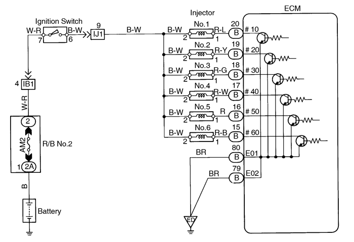
Wiring diagram

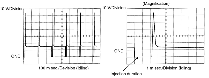
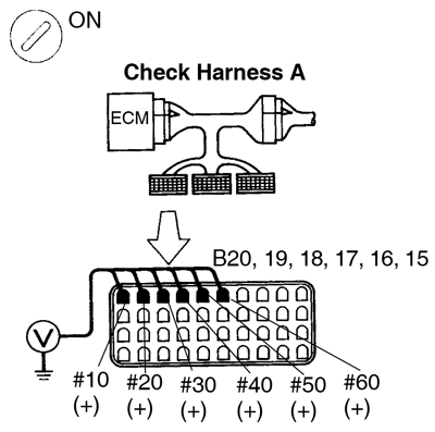
Reference INSPECTION USING OSCILLOSCOPE INJECTOR SIGNAL WAVEFORM
With the engine idling, measure between terminals #10 - #60 and E01 of ECM.
The correct waveform is as shown.

Inspection procedure
| 1 | Check spark plug and spark of misfiring cylinder. | ||
 PREPARATION: PREPARATION:
Check if spark occurs while theengine is being cranked. To prevent excess fuel being injected from the injectors during this test, don’t crank the engine for more than 5 - 10sec. at a time. OK: Spark jumps acrosselectrode gap. | |||
| NG | Replace or check ignition system (See page IG-1). | ||
| OK | |||
| 2 | Check voltage of ECM terminal for injector of failed cylinder. | ||
 PREPARATION: PREPARATION:
Measure voltage between applicable terminal of ECM and body ground. OK: Voltage: 9 - 14 V | |||
| OK | Go to step 4. | ||
| NG | |||
| 3 | Check resistance of injector of misfiring cylinder (See page SF-22). | ||
| NG | Replace injector. | ||
| OK | |||
| Check for open and short in harness and connector between injector and ECM (See page IN-28). | |||
| 4 | Check fuel pressure (See page SF-1). | ||
| NG | Check and repair fuel pump, pressure regulator, fuel pipe line and filter (See page SF-5). | ||
| OK | |||
| 5 | Check injector injection (See page SF-22). | ||
| NG | Replace injector. | ||
| OK | |||
| 6 | Check EGR system (See page EC-7). | ||
| NG | Repair EGR system. | ||
| OK | |||
| 7 | Check mass air flow meter and engine coolant temp. sensor (See page DI-25 , DI-34). | ||
| NG | Repair or replace. | ||
| OK | |||
| Check the compression pressure (See page EM-3), valve clearance (See page EM-4) and valve timing (See page EM-19). | |||
| DTC | P0325 | Knock Sensor 1 Circuit Malfunction |
| DTC | P0330 | Knock Sensor 2 Circuit Malfunction |
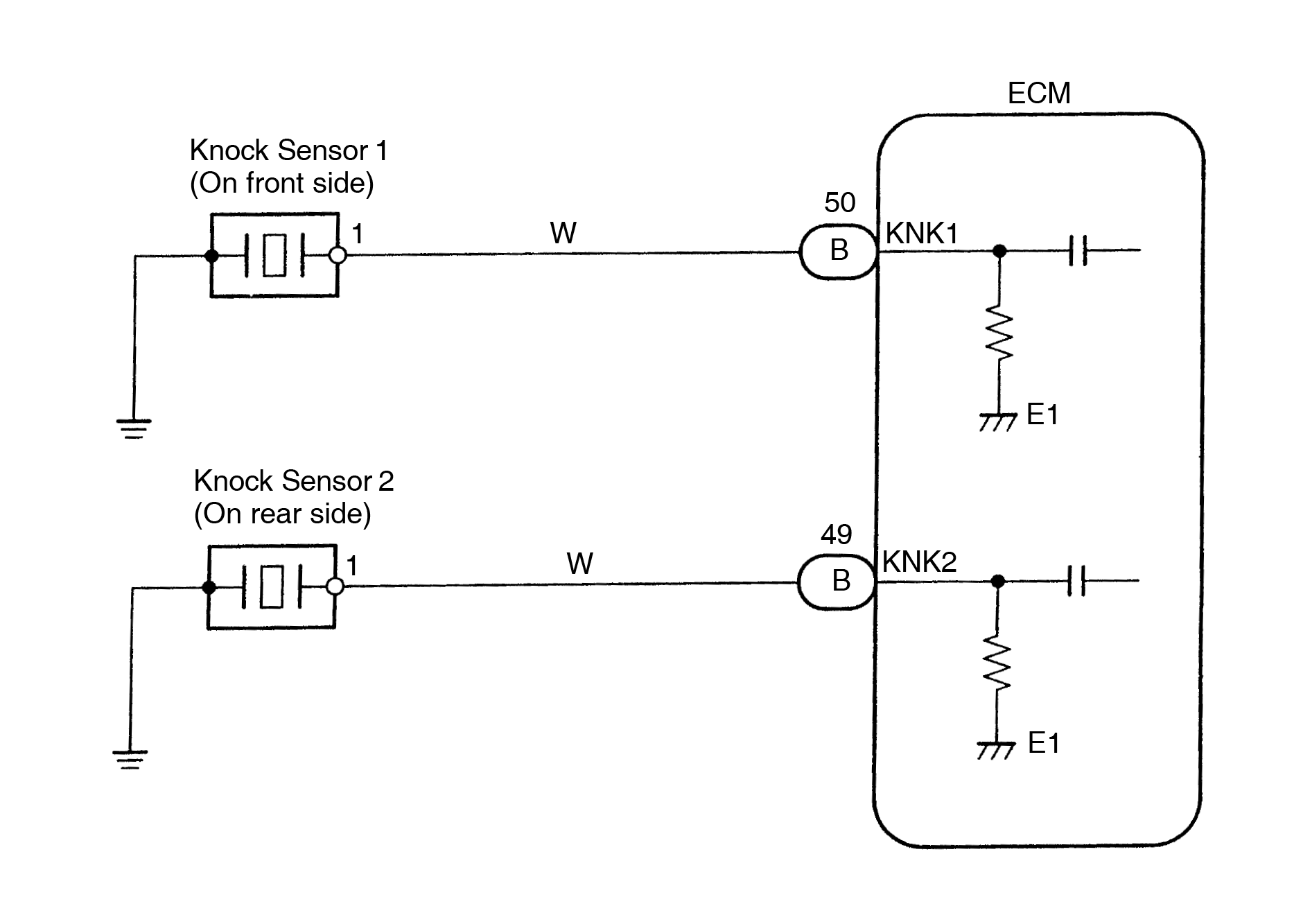
Circuit description
Knock sensors are fitted one each to the front and rear of the left side of the cylinder block to detect engine knocking. This sensor contains a piezoelectric element which generates a voltage when it becomes deformed, which occurs when the cylinder block vibrates due to knocking. If engine knocking occurs, ignition timing is retarded to suppress it.
| DTC No. | DTC Detecting Condition | Trouble Area |
| P0325 | No knock sensor 1 signal to ECM with engine speed between 1,600 rpm and 5,200 rpm |
|
| P0330 | No knock sensor 2 signal to ECM with engine speed between 1,600 rpm and 5,200 rpm |
|
If the ECM detects the above diagnosis conditions, it operates the fail safe function in which the corrective retard angle value is set to the maximum value.
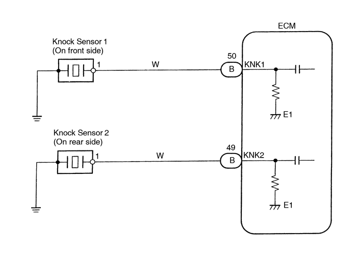
Wiring diagram
Inspection procedure
- DTC P0325 is for the knock sensor circuit on the front side.
- DTC P0330 is for the knock sensor circuit on the rear side.
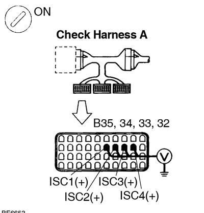
| 1 | Check continuity between terminal KNK1, KNK2 of ECM connector and body, ground. | ||
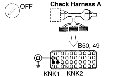 PREPARATION: PREPARATION: Connect Check Harness A to the connectors on the wire harness side (See page DI-20). The other side of Check Harness A is not connected to the ECM terminals. CHECK: Measure resistance between terminal KNK1, KNK2 of ECM connector and body ground. Connect terminal KNK1 to knock sensor 1. OK: Connect terminal KNK2 to knock sensor 2. Resistance: 1 MΩ or higher | |||
| OK | Go to step 3. | ||
| NG | |||
| 2 | Check knock sensor (See page SF-67). | ||
| NG | Replace knock sensor. | ||
| OK | |||
| 3 | Check for open and short in harness and connector between ECM and knock sensor (See page IN-28). | ||
| NG | Repair or replace harness or connector. | ||
| OK | |||
| 4 | Does malfunction disappear when a good knock senor is installed? | ||
| YES | Replace knock sensor. | ||
| NO | |||
| Check and replace ECM (See page IN-28). | |||
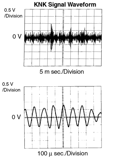
Reference INSPECTION USING OSCILLOSCOPE
- With the engine racing (4,000 rpm) measure waveform between terminals KNK1, KNK2 of ECM and body ground. The correct waveform is as shown.
- Spread the time on the horizontal axis, and confirm that period of the wave is 123 sec. (Normal, mode vibration frequency of knock sensor: 8.1 KHz). If normal mode vibration frequency is not 8.1 KHz, the sensor is malfunctioning.
| DTC | P0335 | Crankshaft Position Sensor ”A” Circuit Malfunction |
Circuit description
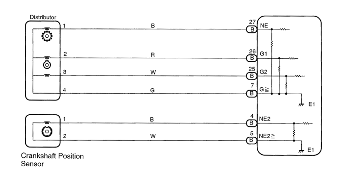
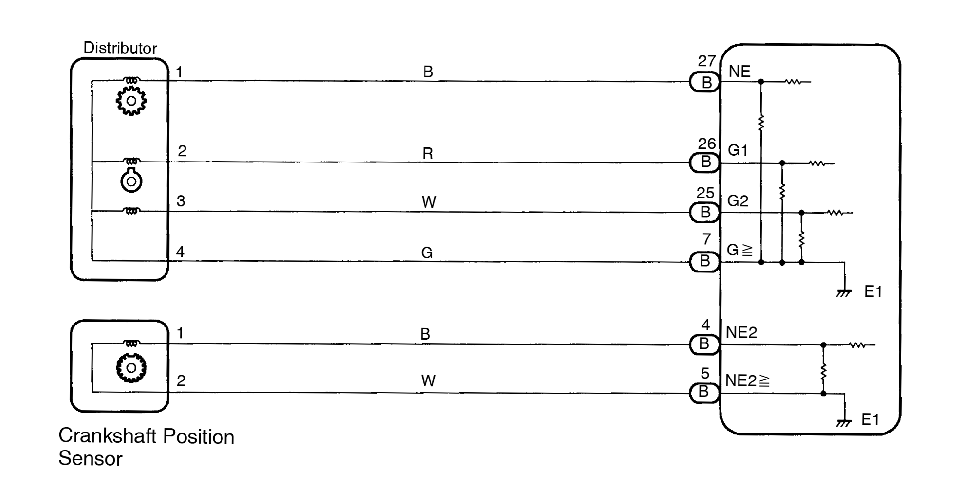
The crankshaft position sensor (NE signal) consists of a signal plate and a pick up coil. The NE signal plate has 24 teeth and is built into the distributor.
When the camshaft rotates, the protrusion on the signal plate and the air gap on the pick up coil change, causing fluctuations in the magnetic field and generating an electromotive force in the pick up coil.
The NE signal sensor generates 24 signals for every engine revolution. The ECM detects the standard crankshaft angle based on the G1, G2 signals, detects the actual crankshaft angle and the engine speed by the NE signals, and detects misfire by NE2 signals.
| DTC No. | DTC Detecting Condition | Trouble Area |
| P0335 | No crankshaft position sensor signal (NE signal) to ECM dur- ing cranking (2 trip detection logic) |
|
| No crankshaft position sensor signal (NE signal) to ECM with engine speed 600 rpm or more (2 trip detection logic) |
Wiring diagram
Inspection procedure
| 1 | Check resistance of crankshaft position sensor for NE signal. | ||||||||
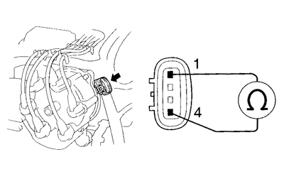 PREPARATION: PREPARATION: Disconnect distributor connector CHECK: Measure resistance between terminals 1 and 4 of distributor connector. OK:
Reference INSPECTION USING OSCILLOSCOPE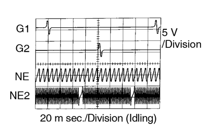
The correct waveforms are as shown. | |||||||||
| NG | Replace distributor housing assembly (See page IG-12). | ||||||||
| OK | |||||||||
| 2 | Check for open and short in harness and connector between ECM and crankshaft position sensor for NE signal (See page IN-28). | ||||||||
| NG | Repair or replace harness or connector. | ||||||||
| OK | |||||||||
| 3 | Check air gap (See page IG-1). | ||||||||
| NG | Replace distributor housing assembly (See page IG-12). | ||||||||
| OK | |||||||||
| Check and replace ECM (See page IN-28). | |||||||||
| DTC | P0340 | Camshaft Position Sensor Circuit Malfunction |
Circuit description
The camshaft position sensors (G1 and G2 signals) consist of a signal plate and a pick up coil.
The G1, G2 signal plates each have one tooth on the outer circumference and are built into the distributor. When the camshaft rotates, the protrusion on the signal plate and the air gap on the pick up coil change, causing fluctuations in the magnetic field and generating an electromotive force in the pick up coil.
The ECM detects the standard crankshaft angle based on the G1, G2 signals, detects the actual crankshaft angle and engine speed by the NE signals, and detects misfire by NE2 signals.
| DTC No. | DTC Detecting Condition | Trouble Area |
| P0340 | No camshaft position sensor signal to ECM with engine speed 600 rpm or more |
|
| No crankshaft position sensor signal (NE2 signal) to ECM during cranking |
Wiring diagram
Refer to page DI-69 for the WIRING DIAGRAM.
Inspection procedure
| 1 | Check resistance of camshaft position sensor. | ||||||||
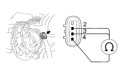 PREPARATION: PREPARATION: Disconnect camshaft position sensor connector. CHECK: Measure resistance between terminals 2, 3 and 4 of distributor connector. OK:
Reference INSPECTION USING OSCILLOSCOPE
| |||||||||
| NG | Replace distributor housing assembly (See page IG-12). | ||||||||
| OK | |||||||||
| 2 | Check for open and short in harness and connector between ECM and camshaft position sensor (See page IN-28). | ||||||||
| NG | Repair or replace harness or connector. | ||||||||
| OK | |||||||||
| 3 | Check air gap (See page IG-1). | ||||||||
| NG | Adjust air gap or replace distributor housing assembly (See page IG-12 ). | ||||||||
| OK | |||||||||
| Check and replace ECM (See page IN-28). | |||||||||
| DTC | P0385 | Crankshaft Position Sensor ”B” Circuit Malfunction |
Circuit description
The crankshaft position sensor (NE2 signal) consists of a signal plate a pick up coil.
The NE2 signal plate has 34 teeth and is mounted on the crankshaft. When the crankshaft rotates, the protrusion on the signal plate and the air gap on the pick up coil change, causing fluctuations in the magnetic field and generating an electromotive force in the pick up coil.
The NE2 signal sensor generates 34 signals for every engine revolution. The ECM detects the standard crankshaft angle based on G1, G2 signals, detects the actual crankshaft angle and the engine speed by NE signals, and detects misfire by NE2 signals.
| DTC No. | DTC Detecting Condition | Trouble Area |
| P0385 | No crankshaft position sensor signal (NE2 signal) to ECM with engine speed 600 rpm or more (2 trip detection logic) |
|
Wiring diagram
Refer to page DI-69 for the WIRING DIAGRAM.
Inspection procedure
| 1 | Check resistance of crankshaft position sensor for NE2 signal. | ||||||||
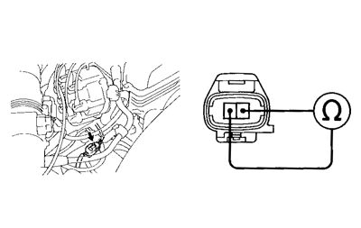 PREPARATION: PREPARATION: Disconnect crankshaft position sensor connector. CHECK: Measure resistance between terminals 1 and 2 of crankshaft position sensor connector. OK:
Reference INSPECTION USING OSCILLOSCOPE
| |||||||||
| NG | Replace crankshaft position sensor (See page IG-19). | ||||||||
| OK | |||||||||
| 2 | Check for open and short in harness and connector between ECM and crankshaft position sensor for NE2 signal (See page IN-28). | ||||||||
| NG | Repair or replace harness or connector. | ||||||||
| OK | |||||||||
| 3 | Inspect sensor installation and teeth of signal plate. | ||||||||
| NG | Tighten the sensor. Replace signal plate (See page IG-19). | ||||||||
| OK | |||||||||
| Check and replace ECM (See page IN-28). | |||||||||
| DTC | P0401 | Exhaust Gas Recirculation Flow Insufficient Detected |
Circuit description
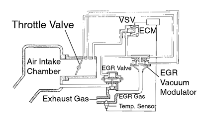
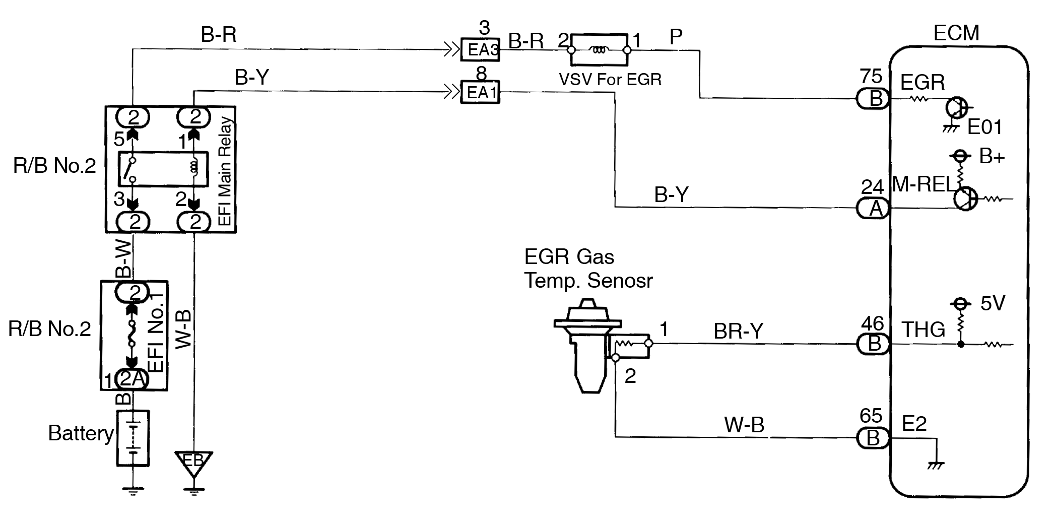
The EGR system recirculates exhaust gas, which is controlled to the proper quantity to suit the driving condi- tions, into the intake air mixture to slow down combustion, reduce the combustion temperature and reduce NOx emissions. The amount of EGR is regulated by the EGR vacuum modulator according to the engine load.
If even one of the following conditions is fulfilled, the VSV is turned ON by a signal from the ECM. This results in atmospheric air acting on the EGR valve, closing the EGR valve and shutting off the exhaust gas (EGR cut-off).
Under the following conditions, EGR is cut to maintain driveability.
- Before the engine is warmed up
- During deceleration (throttle valve closed)
- Light engine load (amount of intake air very small)
- Engine racing.
| DTC No. | DTC Detecting Condition | Trouble Area |
| P0401 | After the engne is warmed up and run at 80 km/h (50 mph) for 3 to 5 min., the EGR gas temperature sensor value does not exceed 40 °C (72 °F) above the ambient air temperature (2 trip detection logic) |
|
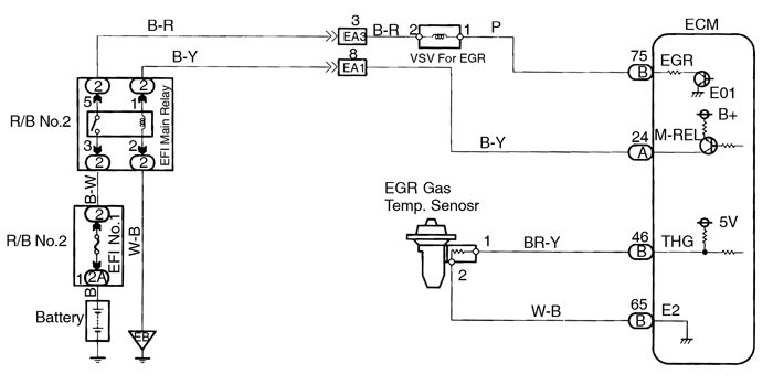
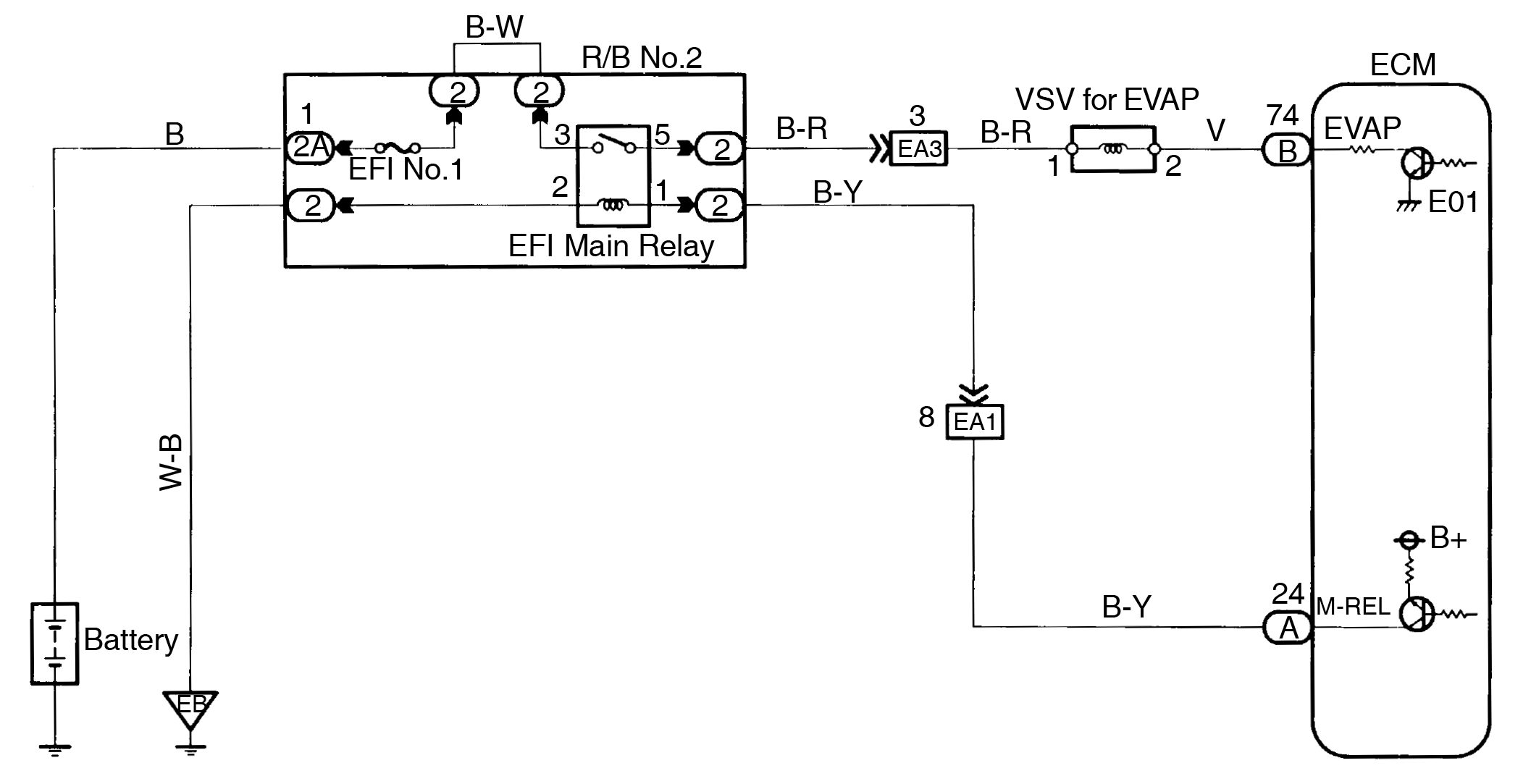
Wiring diagram
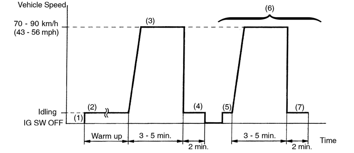
System check driving pattern
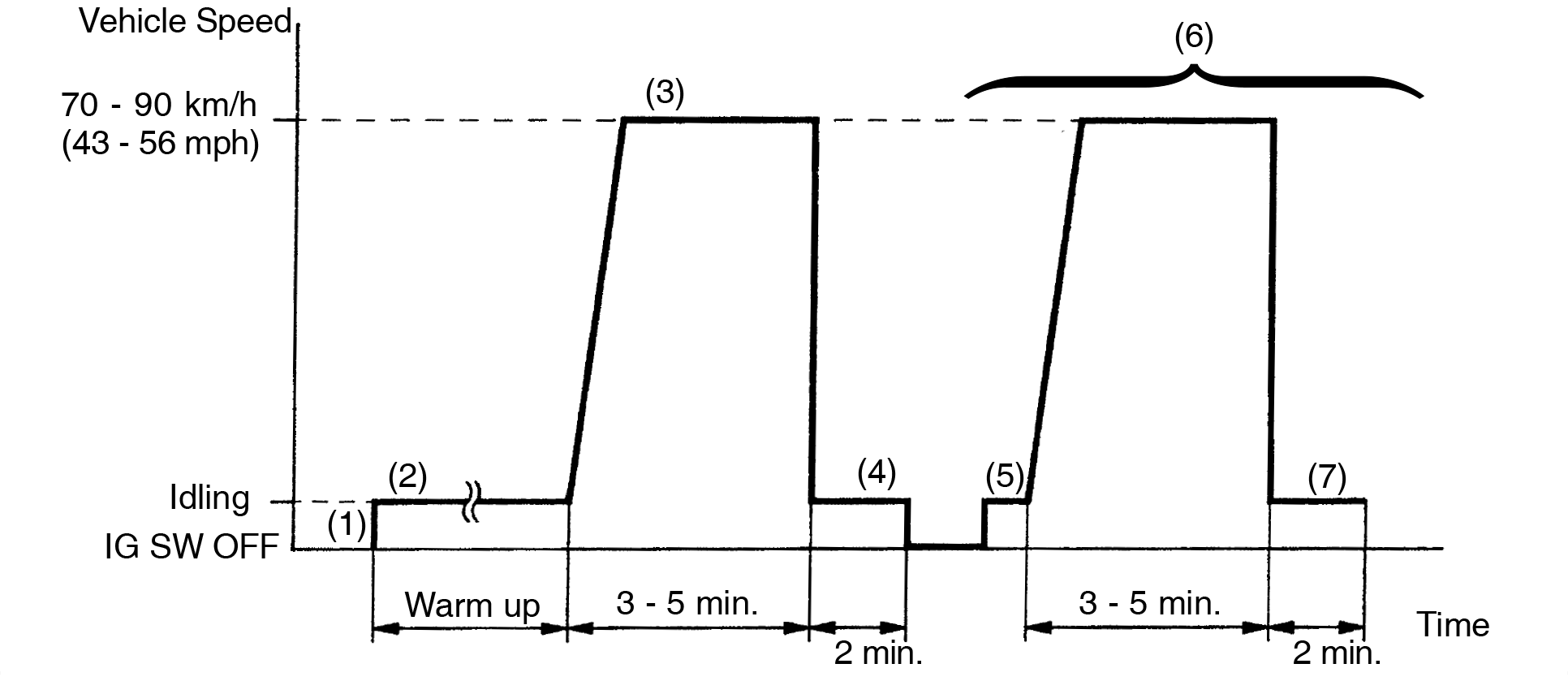
- Connect the OBD II scan tool or TOYOTA hand-held tester to the DLC3.
- Start the engine and warm it up with all accessories switched OFF.
- Run the vehicle at 70 - 90 km/h (43 - 56 mph) for 3 min. or more.
- Idle the engine for about 2 min.
- Stop at safe place and turn the ignition switch OFF.
- Start the engine and do steps (3) and (4) again.
- Check the ”READINESS TESTS” mode on the OBD II scan tool or TOYOTA hand-held tester. If ”COMPL” is displayed and the MIL does not light up, the system is normal. If ”INCMPL” is displayed and the MIL does not light up, run the vehicle again and check it.
”INCMPL” is displayed when either condition (a) or (b) exists.
- The system check is incomplete.
- There is a malfunction in the system.
Inspection procedure
TOYOTA hand-held tester:
| 1 | Connect the TOYOTA hand-held tester and read value of EGR gas temperature. | ||
PREPARATION:
Read EGR gas temperature on TOYOTA hand-held tester. OK: EGR gas temp.: 10°C (50°F) or more If there is an open circuit, the TOYOTA hand-held tester indicates 3.1°C (37.6°F). | |||
| OK | Go to step 4. | ||
| NG | |||
| 2 | Check for open in harness or ECM. | ||
PREPARATION:
Read EGR gas temperature on the TOYOTA hand-held tester. OK: EGR gas temp.: 159.3°C (318.7°F) | |||
| OK | Confirm good connection at sensor. If OK, replace EGR gas temp. sensor (See page EC-7). | ||
| NG | |||
| 3 | Check for open in harness or ECM. | ||
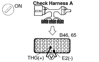
 PREPARATION: PREPARATION:
EGR gas temp. sensor connector is disconnected. Before checking, do a visual check and connect pressure check for the ECM connector (See page IN-28 ). CHECK: Read EGR temperature on the TOYOTA hand-held tester. OK: EGR gas temp.: 159.3°C (318.7°F) | |||
| OK | Open in harness between terminals E2 or THG. Repair or replace harness. | ||
| NG | |||
| Confirm connection at ECM. If OK, replace ECM. | |||
| 4 | Check the connection of the vacuum hose, EGR hose (See page EC-7). | ||
| NG | Repair or replace. | ||
| OK | |||
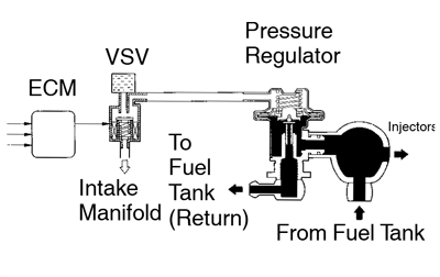
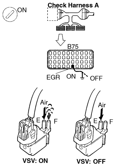
| 5 | Check the VSV for EGR. | ||
| PREPARATION: Select the ACTIVE TEST mode on the TOYOTA hand-held tester. CHECK: Check operation of VSV when it is operated by the TOYOTA hand-held tester. OK: EGR system is OFF: Air from pipe E is flows out through pipe F. EGR system is ON: Air does not flow from pipe E to pipe F. | |||
| OK | Go to step 7. | ||
| NG | |||
| 6 | Check operation of the VSV for EGR (See page SF-61). | ||
| NG | Replace VSV for EGR. | ||
| OK | |||
| Check for open in harness and connector between VSV and ECM (See page IN-28 ). | |||
| 7 | Check EGR vacuum modulator (See page EC-7 ). | ||
| NG | Repair or replace. | ||
| OK | |||
| 8 | Check EGR valve (See page EC-7). | ||
| NG | Repair or replace. | ||
| OK | |||
| 9 | Check value of EGR gas temp. sensor. | ||
PREPARATION:
Measure the EGR gas temp. while racing engine at 4,000 rpm. OK: EGR gas temp. after 3 min.: 140°C (284°F) or more | |||
| NG | Replace EGR gas temp. sensor (See page SF-68). | ||
| OK | |||
| Check and replace ECM (See page IN-28). | |||
OBDII scan tool (excluding TOYOTA hand-held tester)
| 1 | Check resistance of EGR gas temp. sensor. | ||
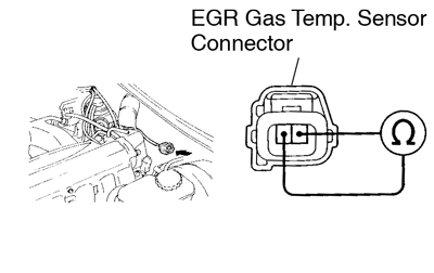 PREPARATION: PREPARATION: Disconnect EGR gas temp. sensor connector. CHECK: Measure resistance between terminals of EGR gas temp. sensor connector. OK: Resistance: 600 kΩ or less. If there is open circuit, ohmmeter indicates 720 kΩ or more. | |||
| NG | Check and replace EGR gas temp. sensor (See page SF-69). | ||
| OK | |||
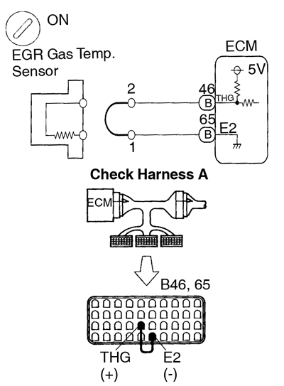
| 2 | Check for open in harness or ECM. | ||
 PREPARATION: PREPARATION:
Measure voltage between terminals of EGR gas temp. sensor wire harness side connector. OK: Voltage: 4.5 - 5.5 V | |||
| OK | Go to step 4 | ||
| NG | |||
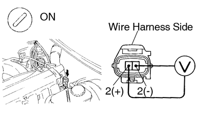
| 3 | Check for open in harness or ECM. | ||
 PREPARATION: PREPARATION:
Measure voltage between terminals of EGR gas temp. sensor wire harness side connector. OK: Voltage: 4.5 - 5.5 V | |||
| OK | Open in harness between terminal E2 or THG. repair or replace harness. | ||
| NG | |||
| Confirm connection at ECM. If OK, replace ECM. | |||
| 4 | Check connection of vacuum hose, EGR hose (See page EC-7). | ||
| NG | Repair or replace. | ||
| OK | |||
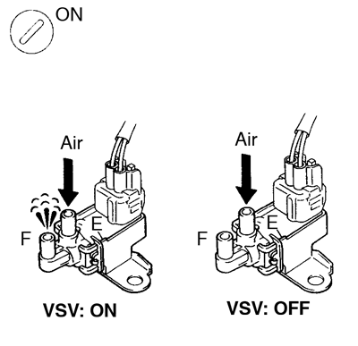
| 5 | Check the VSV for EGR. | ||
 PREPARATION: PREPARATION:
Check VSV function
(1) VSV is ON: Air from pipe E flows out through pipe F. (2) VSV is OFF: Air does not flow from pipe E to pipe F. | |||
| OK | Go to step 7. | ||
| NG | |||
| 6 | Check operation of the VSV for EGR (See page SF-59). | ||
| NG | Replace VSV for EGR. | ||
| OK | |||
| Check for open in harness and connector between engine room R/B and ECM (See page IN-28). | |||
| 7 | Check EGR vacuum modulator (See page EC-7). | ||
| NG | Repair or replace. | ||
| OK | |||
| 8 | Check EGR valve (See page EC-7). | ||
| NG | Repair or replace. | ||
| OK | |||
| 9 | Check resistance of EGR gas temp. sensor. | ||
PREPARATION:
Measure the resistance of the EGR gas temp. sensor while racing the engine at 4,000 rpm. OK: Resistance of EGR gas temp. senor after 3 min. 4.3 kΩ or less Resistance: 188.6 - 439.0 kΩ at 20°C (68°F). | |||
| NG | Replace EGR gas temp. sensor (See page SF-68). | ||
| OK | |||
| Check and replace ECM (See page IN-28). | |||
| DTC | P0402 | Exhaust Gas Recirculation Flow Excessive Detected |
Circuit description
Refer To Exhaust Gas Recirculation Flow Insufficient Detected on page DI-78.
| DTC No. | DTC Detecting Condition | Trouble Area |
| P0402 | EGR gas temp. sensor value is high during EGR cut-off when engine is cold (Race engine at about 4,000 rpm without load do that vacuum is applied to port E) (2 trip detection logic) |
|
| EGR valve is always open (2 trip detection logic) |
Inspection procedure
TOYOTA hand-held tester
| 1 | Connect the TOYOTA hand-held tester and read EGR gas temperature value. | ||
PREPARATION:
Read EGR gas temperature on the TOYOTA hand-held tester. OK: EGR gas temp.: 150°C (302°F) or less. (Not immediately after driving) If there is a short circuit, the TOYOTA hand-held tester indicates 159.3°C (318.7°F). | |||
| OK | Go to step 4. | ||
| NG | |||
| 2 | Check for short in harness and ECM. | ||
| PREPARATION: Disconnect the EGR gas temp. sensor connector. CHECK: Read EGR gas temp. on the TOYOTA hand-held tester. OK: EGR gas temp.: 3.1°C (37.6°F) | |||
| OK | Replace EGR gas temp. sensor (See page SF-68 ). | ||
| NG | |||
| 3 | Check for short in harness or ECM. | ||
PREPARATION:
CHECK: Read EGR gas temp. on the TOYOTA hand-held tester. OK: EGR gas temp.: 3.1°C (37.6°F) | |||
| OK | Repair or replace harness or connector. | ||
| NG | |||
| Check and replace ECM (See page IN-28). | |||
| 4 | Check the VSV for EGR (See page DI-78 , step 5). | ||
| OK | Check EGR valve (See page EC-7). | ||
| NG | |||
| 5 | Check operation of the VSV for EGR (See page SF-59 ). | ||
| NG | Replace VSV for EGR. | ||
| OK | |||
| Check for short in harness and connector between VSV and ECM (See page ). | |||
OBDII scan tool (excluding TOYOTA hand-held tester)
| 1 | Check resistance of EGR gas temp. sensor. | ||
| PREPARATION: Disconnect EGR gas temp. sensor connector. CHECK: Measure resistance between terminals of EGR gas temp. sensor connector. OK: Resistance: 2.5 kΩ or more. (Not immediately after driving) If there is short circuit, ohmmeter indicates 200Ω or less. | |||
| NG | Replace EGR gas temp. sensor (See page SF-68). | ||
| OK | |||
| 2 | Check for short in harness and connector between EGR gas temp. sensor and ECM (See page IN-18). | ||
| NG | Repair or replace harness or connector. | ||
| OK | |||
| 3 | Check the VSV for EGR (See page DI-78 , step 5). | ||
| OK | Check EGR valve (See page EC-7 ). | ||
| NG | |||
| 4 | Check operation of the VSV for EGR (See page SF-59 ). | ||
| NG | Replace VSV for EGR. | ||
| OK | |||
| 5 | Check for short in harness and connector between VSV and ECM (See page IN-28). | ||
| NG | Repair or replace harness or connector. | ||
| OK | |||
| Check and replace ECM (See page IN-28 ). | |||
| DTC | P0420 | Catalyst System Efficiency Below Threshold |
Circuit description
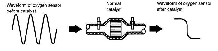
The ECM compares the waveform of the oxygen sensor located before the catalyst with the waveform of the oxygen sensor located after the catalyst to determine whether or not catalyst performance has deteriorated.
Air-fuel ratio feedback compensation keeps the waveform of the oxygen sensor before the catalyst repeatedly changing back and forth from rich to lean.
If the catalyst is functioning normally, the waveform of the oxygen sensor after the catalyst switches back and forth between rich and lean much more slowly than the waveform of the oxygen sensor before the catalyst.
But when both wavaforms change at a similar rate, it indicates that catalyst performance has deteriorated.

| DTC No. | DTC Detecting Condition | Trouble Area |
| P0420 | After the engine and the catalyst are warmed up, and while the vehicle is driven within the set vehicle and engine speed range, the waveforms of the heated oxygen sensors (bank 1, 2 sen- sor 1 and bank 1 sensor 2) have the same amplitude (2 trip detection logic) |
|
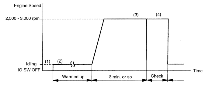
Confirmation engine racing pattern

- Connect the TOYOTA hand-held tester to the DLC3, or connect the probe of the oscilloscope between terminals OX1, OX2, OX3 and E1 of ECM.
- Start engine and warm it up with all accessories switched OFF until water temperature is stable.
- Race the engine at 2,500 - 3,000 rpm for about 3 min.
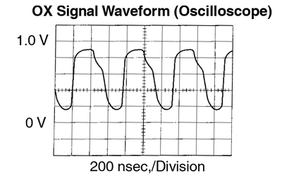
- After confirming that the waveforms of the heated oxygen sensors, bank 1, 2 sensor 1 (OX1, OX2), oscillate around 0.5 V during feedback to the ECM, check the waveform of the heated oxygen senor, bank 1 sensor 2 (OX3).
If there is a malfunction in the system, the waveform of the heated oxygen senor, bank1 sensor 2 (OX3), is almost the same as that of the heated oxygen sensors, bank 1, 2 senor 1 (OX1, OX2), on the left.
There are some cases where, even though a malfunction exists, the MIL may either light up or not light up.
There are some cases where, even though a malfunction exists, the MIL may either light up or not light up.
Inspection procedure
| 1 | Are there any other code (besides DTC P0420) being output? | ||
| YES | Go to relevant DTC chart. | ||
| NO | |||
| 2 | Check heated oxygen senor (bank 1, 2 sensor 1) (See page DI-48). | ||
| NG | Repair or replace. | ||
| OK | |||
| 3 | Check heated oxygen senor (bank1 sensor 2) (See page DI-48 ). | ||
| NG | Repair or replace. | ||
| OK | |||
| Replace three-way catalytic converter (See page DI-55). | |||
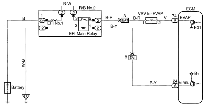
| DTC | P0441 | Evaporative Emission Control System Incorrect Purge Flow |
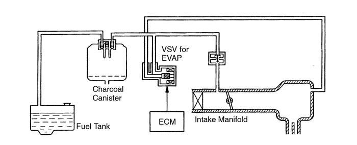
Circuit description
To reduce HC emissions, evaporated fuel from the fuel tank is routed through the charcoal canister to the intake manifold for combustion in the cylinders.
The ECM changes the duty signal to the VSV for EVAP so that the intake quantity of HC emissions is appropriate for the driving conditions (engine load, engine speed, etc.) after the engine is warme up.

| DTC No. | DTC Detecting Condition | Trouble Area |
| P0441 | The proper response to the computer command does not oc- cur (2 trip detection logic) |
|
Wiring diagram
Inspection procedure
TOYOTA hand-held tester
| 1 | Connector the TOYOTA hand-held tester and check operation of VSV for EVAP. | ||
 PREPARATION: PREPARATION:
Check operation of VSV when VSV is operated by the TOYOTA hand-held tester. OK: VSV is ON: Air from pipe E flows out through pipe F. VSV is OFF: Air does not flow from pipe E to pipe F. | |||
| OK | Go to step 4. | ||
| NG | |||
| 2 | Check VSV for EVAP (See page SF-61 ). | ||
| NG | Replace VSV for EVAP. | ||
| OK | |||
| 3 | Check for open and short in harness and connector between EFI main relay and ECM (See page IN-28 ). | ||
| NG | Repair or replace harness or connector. | ||
| OK | |||
| Check and replace ECM (See page IN-28 ). | |||
| 4 | Check connection of vacuum hose (See page EC-5 ). | ||
| NG | Repair or replace. | ||
| OK | |||
| Check and repair charcoal canister (See page EC-5 ). | |||
OBDII scan tool (excluding TOYOTA hand-held tester)
| 1 | Check VSV for EVAP (See page SF-61 ). | ||
| NG | Replace VSV for EVAP. | ||
| OK | |||
| 2 | Check voltage between terminal EVAP of ECM connector and body ground. | ||
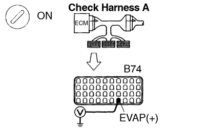 PREPARATION: PREPARATION:
Measure voltage between terminal EVAP of ECM connector and body ground. OK: Voltage: 9 - 14 V | |||
| NG | Check and repair harness or connector. | ||
| OK | |||
| 3 | Check connection of vacuum hose (See page EC-5 ). | ||
| NG | Repair or replace. | ||
| OK | |||
| 4 | Check charcoal canister (See page EC-5 ). | ||
| NG | Repair or replace. | ||
| OK | |||
| Check and replace ECM (See page IN-28 ). | |||
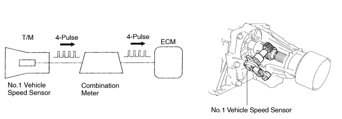
| DTC | P0500 | Vehicle Speed Sensor Malfunction |
Circuit description
The No.1 vehicle speed senor outputs a 4-pulse signal for every revolution of the rotor shaft, which is rotated by the transmission output shaft via the driven gear. After this signal is converted into a more precise rectangular waveform by the waveform shaping circuit inside the combination meter, it is then transmitted to the ECM. The ECM determines the vehicle speed based on the frequency of these pulse signals.

| DTC No. | DTC Detecting Condition | Trouble Area |
| P0500 | No vehicle speed sensor signal to ECM under the following conditions: (2 trip detection logic) For A/T:
|
|
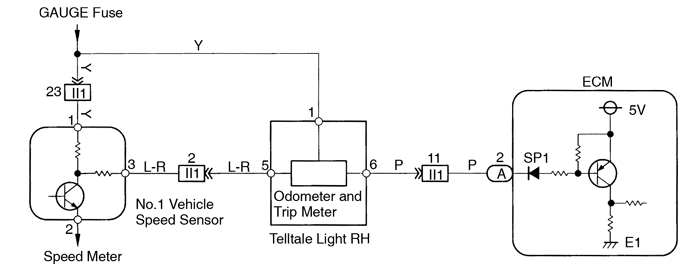
Wiring diagram

Inspection procedure
| 1 | Check operation of speedometer. | ||
| CHECK: Drive the vehicle and check if the operation of the speedometer in the combination meter is normal. The No.1 vehicle speed sensor is operating normally if the speedometer display is normal. | |||
| NG | Check speedometer circuit (See page BE-40 ). | ||
| OK | |||
| 2 | Check voltage between terminal SP1 of ECM connector and body ground. | ||
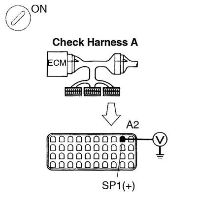 PREPARATION: PREPARATION:
Measure voltage between terminal SP1 of ECM connector and body ground when wheel is turned slowly. OK: Voltage is generated intermittently. 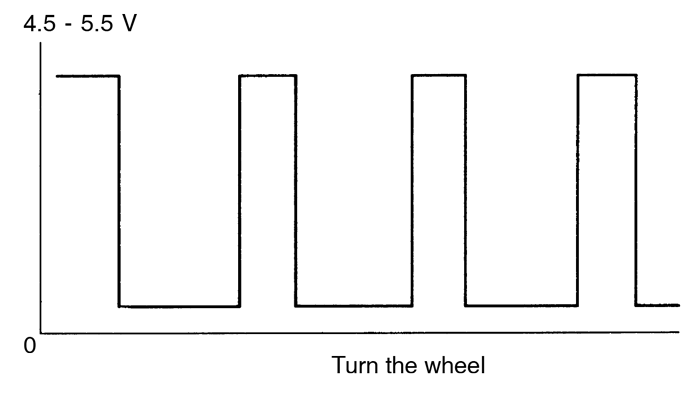 | |||
| NG | Check and repair harness and connector between combination meter and ECM. | ||
| OK | |||
| Check and replace ECM (See page IN-28 ). | |||
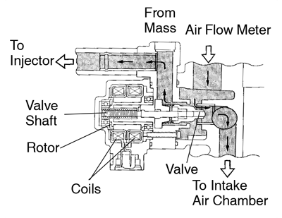
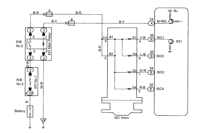
| DTC | P0505 | Idle Control System Malfunction |
Circuit description
The step motor type IAC valve is located in front of the intake air chamber. Intake air bypassing the throttle valve is directed to the IAC valve through a passage. A step motor is built into the IAC valve. It consists of 4 coils, a magnetic rotor, valve shaft and valve.
When current flows to the coils due to signals from the ECM, the rotor turns and moves the valve shaft forward or backward, changing the clearance between the valve and valve seat. In this way the intake air volume bypassing the throttle valve is regulated, controlling the engine speed.
There are 125 possible positions to which the valve can be opened.
| DTC No. | DTC Detecting Condition | Trouble Area |
| P0505 | Idle speed continues to vary greatly from the target speed (2 trip detection logic) |
|
Wiring diagram
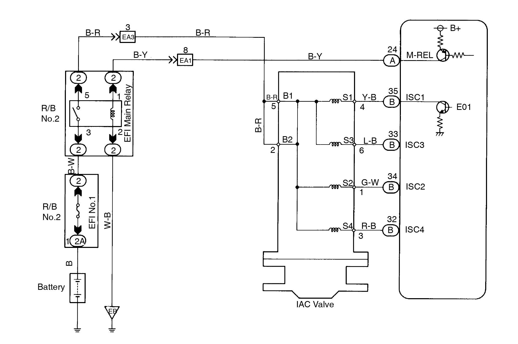
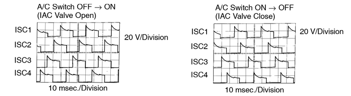
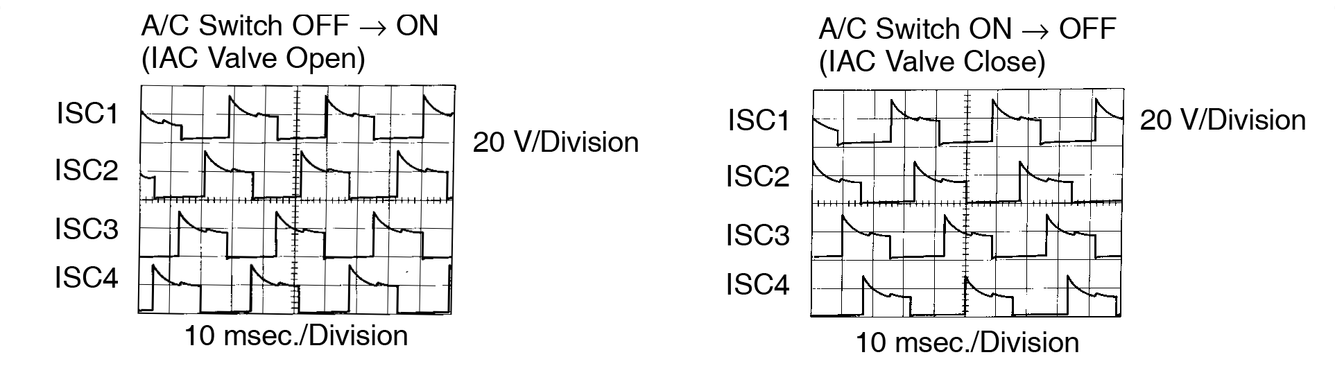
Reference INSPECTION USING OSCILLOSCOPE
- With engine idling measure waveforms between terminals ISC1, ISC2, ISC3, ISC4 and E01 of ECM when A/C switch ON or OFF.
The correct waveforms are as shown.
Inspection procedure
| 1 | Check air induction system (See page SF-1). | ||
| NG | Repair or replace. | ||
| OK | |||
| 2 | Check voltage between terminals ISC1, ISC2, ISC3, ISC4 of ECM connector and body ground. | ||
 PREPARATION: PREPARATION:
Measure voltage between terminals ISC1, ISC2, ISC3, ISC4 of ECM connector and body ground. OK: Voltage: 9 - 14 V | |||
| OK | Go to step 4. | ||
| NG | |||
| 3 | Check IAC valve (See page SF-45 ). | ||
| NG | Replace IAC valve. | ||
| OK | |||
| Check for open and short in harness and connector between EFI main relay (Marking: EFI MAIN) and IAC valve, IAC valve and ECM (See page IN-28 ). | |||
| 4 | Check operation of the IAC valve (See page SF-45 ). | ||
| NG | Repair or replace IAC valve. | ||
| OK | |||
| Check and replace ECM (See page IN-28 ). | |||
| DTC | P0510 | Closed Throttle Position Switch Malfunction |
Circuit description
Refer to Throttle/Pedal Position Sensor/Switch ”A” Circuit Malfunction on page DI-40 .
| DTC No. | DTC Detecting Condition | Trouble Area |
| P0510 | The closed throttle position switch does not turn ON or OFF even once when the vehicle is driven (2 trip detection logic) |
|
After confirming DTC P0510 use the TOYOTA hand-held tester to confirm closed throttle position switch signal from ”CURRENT DATE”.
| Throttle Valve | Closed throttle position switch signal | Malfunction |
| Fully Closed | OFF | Open Circuit |
| Fully Open | ON | Short Circuit |
Wiring diagram
Refer to page DI-40 for the WIRING DIAGRAM.Inspection procedure
If DTC P0110, P0115 and P0120 are output simultaneously, E2 (sensor ground) may be open.TOYOTA hand-held tester
| 1 | Connect the TOYOTA hand-held tester and read CTP switch signal. | |||||||||||
PREPARATION:
Read CTP switch signal on the TOYOTA hand-held tester. RESULT:
| ||||||||||||
| 2 | Check for open in harness or ECM. | |||||||||||
 PREPARATION: PREPARATION:
Read CTP switch signal on the TOYOTA hand-held tester. OK: CTP switch signal: ON | ||||||||||||
| OK | Confirm good connection at sensor. If OK, replace throttle position sensor (See page SF-42 ). | |||||||||||
| NG | ||||||||||||
| 3 | Check for open in harness or ECM. | |||||||||||
 PREPARATION: PREPARATION:
Read CTP switch signal on the TOYOTA hand-held tester. OK: CTP switch signal: ON | ||||||||||||
| OK | Open in harness between ECM and throttle position sensor, repair or replace harness. | |||||||||||
| NG | ||||||||||||
| Confirm connection at ECM. If OK, replace ECM. | ||||||||||||
| 4 | Check for short in harness or ECM. | |||||||||||
 PREPARATION: PREPARATION:
Read CTP switch signal on the TOYOTA hand-held tester. OK: CTP switch signal: OFF | ||||||||||||
| OK | Confirm good connection at sensor. If OK, replace throttle position sensor (See page SF-42 ). | |||||||||||
| NG | ||||||||||||
| 5 | Check for short in harness or ECM. | |||||||||||
 PREPARATION: PREPARATION:
Read CTP switch signal on the TOYOTA hand-held tester. OK: CTP switch signal: OFF | ||||||||||||
| OK | Short in harness between ECM and throttle position sensor, repair or replace harness. | |||||||||||
| NG | ||||||||||||
| Confirm connection at ECM. If OK, replace ECM. | ||||||||||||
OBDII scan tool (excluding TOYOTA hand-held tester)
| 1 | Check for open and short in harness or ECM. | ||
 PREPARATION: PREPARATION:
Measure voltage between terminals 1 and 2 of throttle position sensor connector. OK: Voltage: 9 - 14 V | |||
| OK | Confirm good connection at sensor. If OK, replace throttle position sensor (See page SF-42 ). | ||
| NG | |||
| 2 | Check for open and short in harness and connector between throttle position sensor and ECM (See page IN-28 ). | ||
| NG | Open or short in harness between ECM and throttle position sensor. | ||
| OK | |||
| Confirm connection at ECM. If OK, replace ECM. | |||
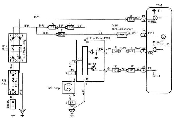
| DTC | P1200 | Fuel Pump Relay/ECU Circuit Malfunction |
Circuit description
The fuel pump speed is controlled at 2 steps (high speed, low speed) by the condition of the engine (starting, light load, heavy load), when the engine starts (STA ON), the ECM sends a Hi signal (about 5 V) to the fuel pump ECU (FPC terminal).
The fuel pump ECU then outputs Hi voltage (battery positive voltage) to the fuel pump so that the fuel pump operates at high speed.
After the engine starts, during idling or light loads, the ECM outputs a Low signal (about 2.5 V) to the fuel pump ECU, the fuel pump ECU outputs Low voltage (about 9 V) to the fuel pump and causes the fuel pump to operate at low speed.
If the intake air volume increases (high engine load), the ECM sends a Hi signal to the fuel pump ECU and causes the fuel pump to operate at high speed.
| DTC No. | DTC Detecting Condition | Trouble Area |
| P1200 | Open or short in fuel pump circuit for 1 sec. or more with en- gine speed 1,000 rpm or less (2 trip detection logic) |
|
| Open in input circuit of fuel pump ECU (FPC) with engine speed 1,000 rpm or less (2 trip detection logic) | ||
| Open or short in diagnostic signal line (DI) of fuel pump ECU with engine speed 1,000 rpm or less (2 trip detection logic) |
Wiring diagram
Inspection procedure
| 1 | Check operation of fuel pump (See page SF-5 ). | ||
| OK | Go to step 7. | ||
| NG | |||
| 2 | Check voltage of fuel pump ECU power source. | ||
 PREPARATION: PREPARATION:
Measure voltage between terminal 4 of fuel pump ECU connector and body ground. OK: Voltage: 9 - 14 V | |||
| NG | Check for open and short in harness and connector between EFI main relay (Marking: EFI MAIN) and fuel pump ECU (See page IN-28 ). | ||
| OK | |||
| 3 | Check voltage between terminals 1 and 3 of fuel pump ECU connector. | ||
 PREPARATION: PREPARATION:
Measure voltage between terminals 1 and 3 of fuel pump ECU connector when ignition switch is turned to start. OK: Voltage: 4.5 - 5.5 V | |||
| OK | Go to step 5. | ||
| NG | |||
| 4 | Check for open and short in harness and connector between terminals FPC of ECM and 3 of fuel pump ECU, terminal 1 of fuel pump ECU and body ground (See page IN-28 ). | ||
| NG | Repair or replace harness or connector. | ||
| OK | |||
| Check and replace ECM. | |||
| 5 | Check fuel pump (See page SF-5 ). | ||
| NG | Repair or replace fuel pump. | ||
| OK | |||
| 6 | Check for open and short in harness and connector between terminal 5 of fuel pump ECU and fuel pump, fuel pump and body ground (See page IN-28 ). | ||
| NG | Repair or replace harness or connector. | ||
| OK | |||
| Replace fuel pump ECU. | |||
| 7 | Check for open and short in harness and connector between terminals DI of ECM and 2 of fuel pump ECU (See page IN-28 ). | ||
| NG | Repair or replace harness or connector. | ||
| OK | |||
| Check and replace ECM. | |||
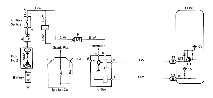
| DTC | P1300 | Igniter Circuit Malfunction |
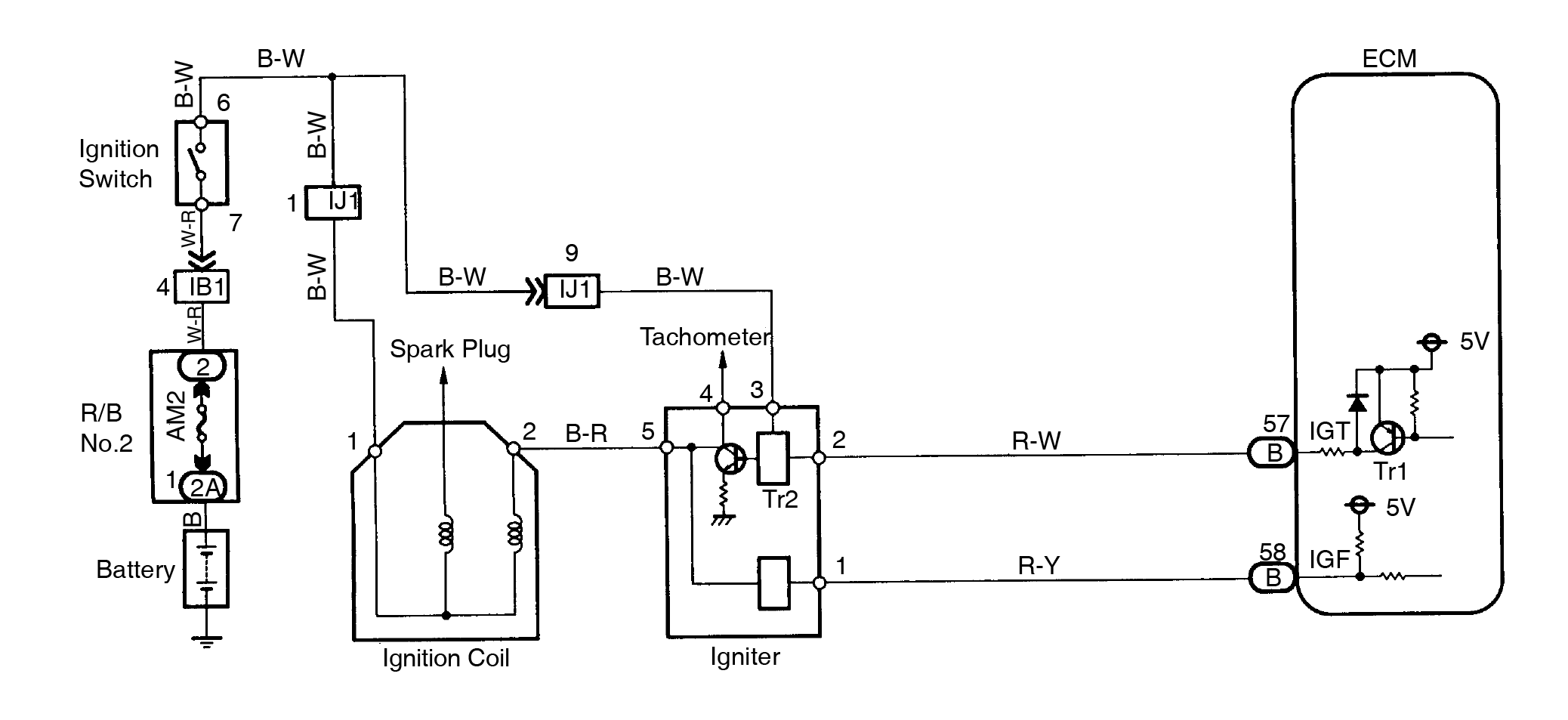
Circuit description
The ECM determines the ignition timing, turns on Tr1 at a predetermined angle (°CA) before the desired ignition timing and outputs an ignition signal (IGT) ”1” to the igniter.
Since the width of the IGT signal is constant, the dwell angle control circuit in the igniter determines the time the control circuit starts primary current flow to the ignition coil based on the engine rpm and ignition timing one revolution ago, that is, the time the Tr2 turns on.
When it reaches the ignition timing, the ECM turns Tr1 off and outputs the IGT signal ”0”.
This turns Tr2 off, interrupting the primary current flow and generating a high voltage in the secondary coil which causes the spark plug to spark. Also, by the counter electromotive force generated when the primary current is interrupted, the igniter sends an ignition confirmation signal (IGF) to the ECM.
The ECM stops fuel injection as a fail safe function when the IGF signal is not input to the ECM.
| DTC No. | DTC Detecting Condition | Trouble Area |
| P1300 | No IGF signal to ECM for 12 consecutive IGT signals during engine running |
|
Wiring diagram
Inspection procedure
| 1 | Check spark plug and spark of misfiring cylinder (See page DI-60 ). | ||
| NG | Go to step 4. | ||
| OK | |||
| 2 | Check for open and short in harness and connector in IGF signal circuit between ECM and igniter (See page IN-28 ). | ||
| NG | Repair or replace harness or connector. | ||
| OK | |||
| 3 | Disconnect igniter connector and check voltage between terminal IGF of ECM connector and body ground. | ||
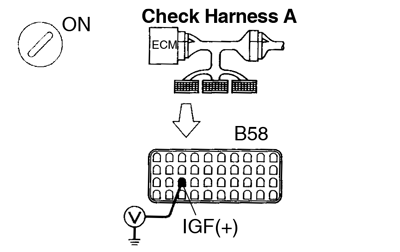 PREPARATION: PREPARATION:
Measure voltage between terminal IGF of ECM connector and body ground. OK: Voltage: 4.5 - 5.5 V | |||
| OK | Replace igniter (See page IG-1 ). | ||
| NG | |||
| Check and replace ECM (See page IN-28 ). | |||
| 4 | Check for open and short in harness and connector in IGT signal circuit between ECM and igniter (See page IN-18 ). | ||
| NG | Repair or replace harness or connector. | ||
| OK | |||
| 5 | Check voltage between terminal IGT of ECM connector and body ground. | ||
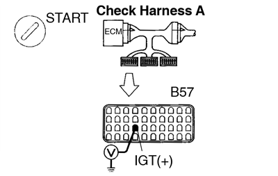 PREPARATION: PREPARATION: Connect Check Harness A (See page DI-20 ). CHECK: Measure voltage between terminal IGT of ECM connector and body ground when engine is cranked. OK: Voltage: More than 0.1 V and less than 4.5 V Reference INSPECTION USING OSCILLOSCOPE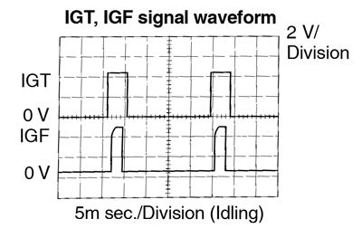
The correct rectangular waveforms are as shown. | |||
| NG | Check and replace ECM (See page IN-28 ). | ||
| OK | |||
| 6 | Disconnect igniter connector and check voltage between terminal IGT of ECM connector and body ground. | ||
PREPARATION:
Measure voltage between terminal IGT of ECM connector and body ground when engine is cranked. OK: Voltage: More than 0.1 V and less than 4.5 V | |||
| NG | Check and replace ECM (See page IN-28 ). | ||
| OK | |||
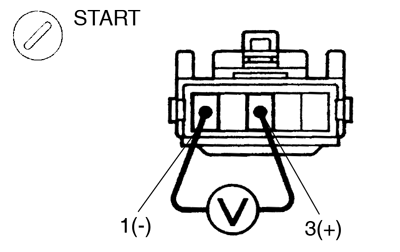
| 7 | Check voltage between terminal 3 of igniter connector and body ground. | ||
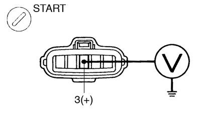 PREPARATION: PREPARATION: Disconnect igniter connector. CHECK: Measure voltage between terminal 3 of igniter connector and body ground, when ignition switch is turned to ”ON” and ”START” position. OK: Voltage: 9 - 14 V | |||
| NG | Check and repair igniter power source circuit. | ||
| OK | |||
| 8 | Check for open and short in harness and connector between ignition switch and ignition coil, ignition coil and igniter (See page IN-28 ). | ||
| NG | Repair or replace harness or connector. | ||
| OK | |||
| 9 | Check ignition coil (See page IG-1 ). | ||
| NG | Replace ignition coil | ||
| OK | |||
| Replace igniter. | |||
| DTC | P1335 | Crankshaft Position Sensor Circuit Malfunction (during engine running) |
Circuit description
Refer to Crankshaft Position Sensor ”A” Circuit Malfunction on page DI-69 .
| DTC No. | DTC Detecting Condition | Trouble Area |
| P1335 | No crankshaft position sensor signal (NE signal) to ECM with engine speed 1,000 rpm or more |
|
See DTC P0335 for the WIRING DIAGRAM and INSPECTION PROCEDURE.
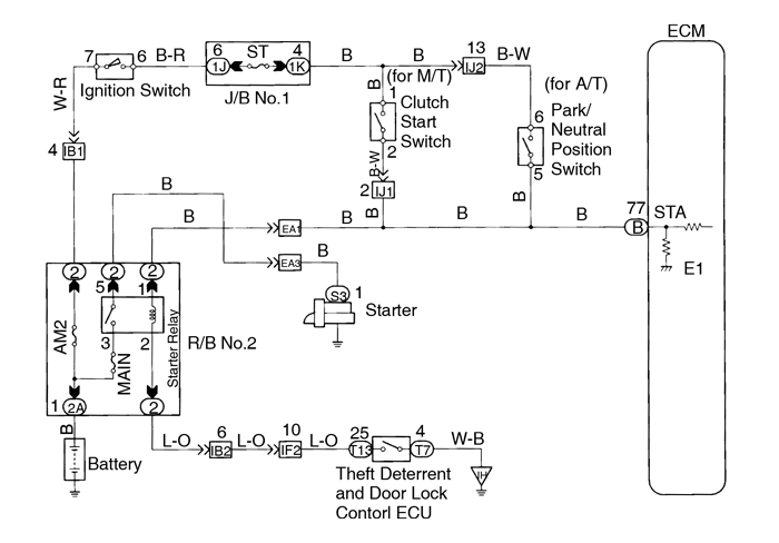
| DTC | P1500 | Starter Signal Circuit Malfunction |
Circuit description
When the engine is cranked, the intake air flow is slow, so fuel vaporization is poor. A rich mixture is therefore necessary in order to achieve good startability. While the engine is being cranked, the battery voltage is applied to terminal STA of the ECM. The starter signal is mainly used to increase the fuel injection volume for the starting injection control and after-start injection control.
| DTC No. | DTC Detecting Condition | Trouble Area |
| P1500 | No starter signal to ECM |
|
In this circuit, diagnosis can only be made in the check mode.
Wiring diagram

Inspection procedure
This diagnostic chart is based on the premise that the engine is cranked normally. If the engine is not ranked, proceed to the matrix chart of problem symptoms on page DI-24 .
| 1 | Connect the TOYOTA hand-held tester and check STA signal. | ||||||||
PREPARATION:
Read STA signal on the TOYOTA hand-held tester while starter operates. OK:
| |||||||||
| OK | Proceed to next circuit inspection shown on matrix chart (See page DI-24 ). | ||||||||
| NG | |||||||||
| 2 | Check for open in harness and connector between ECM and starter relay (See page IN-28 ). | ||||||||
| NG | Repair or replace harness or connector. | ||||||||
| OK | |||||||||
| Check and replace ECM (See page IN-28 ). | |||||||||
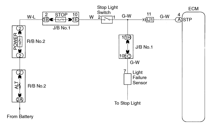
| DTC | P1520 | Stop Light Switch Signal Malfunction Only for A/T |
Circuit description
This signal is used to detect when the brakes have been applied. The STP signal voltage is the same as the voltage supplied to the stop lights.
The STP signal is used mainly to control the fuel cut-off engine speed. (The fuel cut-off engine speed is reduced slightly when the vehicle is braking.)
| DTC No. | DTC Detecting Condition | Trouble Area |
| P1520 | The stop light switch does not turn off even once the vehicle is driven. (2 trip detection logic) |
|
Wiring diagram

Inspection procedure
| 1 | Check operation of stop light. | ||||||||
| CHECK: Check if the stop lights go on and off normally when the brake pedal is operated and released. | |||||||||
| NG | Check and repair stop light circuit (See page BE-33 ). | ||||||||
| OK | |||||||||
| 2 | Check STP signal. | ||||||||
When using TOYOTA hand-held tester: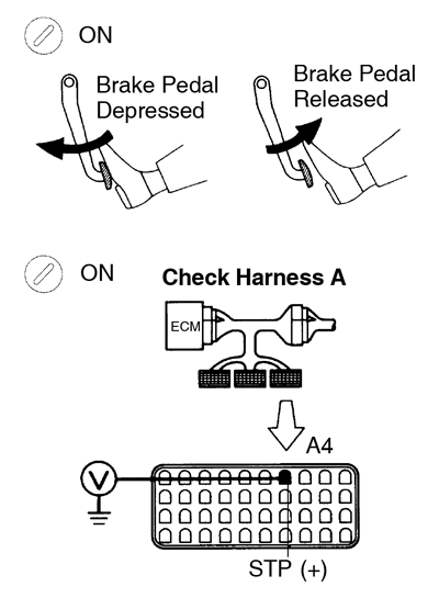 PREPARATION: PREPARATION:
Read the STP signal on the TOYOTA hand-held tester. OK: Break pedal is depressed: STP ... ON Break pedal is released: STP ... OFF When not using TOYOTA hand-held tester:PREPARATION:Connect Check Harness A (See page DI-20 ). CHECK:
| |||||||||
| OK | Check for intermittent problems (See page DI-3 ). | ||||||||
| NG | |||||||||
| 3 | Check harness and connector between ECM and stop light switch (See page IN-28 ). | ||||||||
| NG | Repair or replace harness or connector. | ||||||||
| OK | |||||||||
| Check and replace ECM. | |||||||||
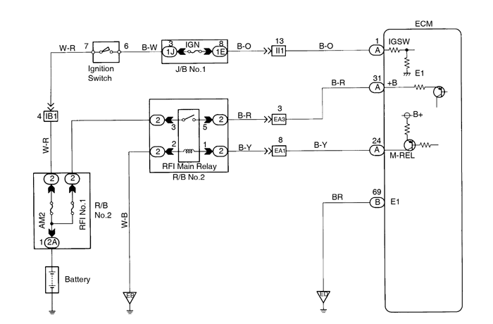
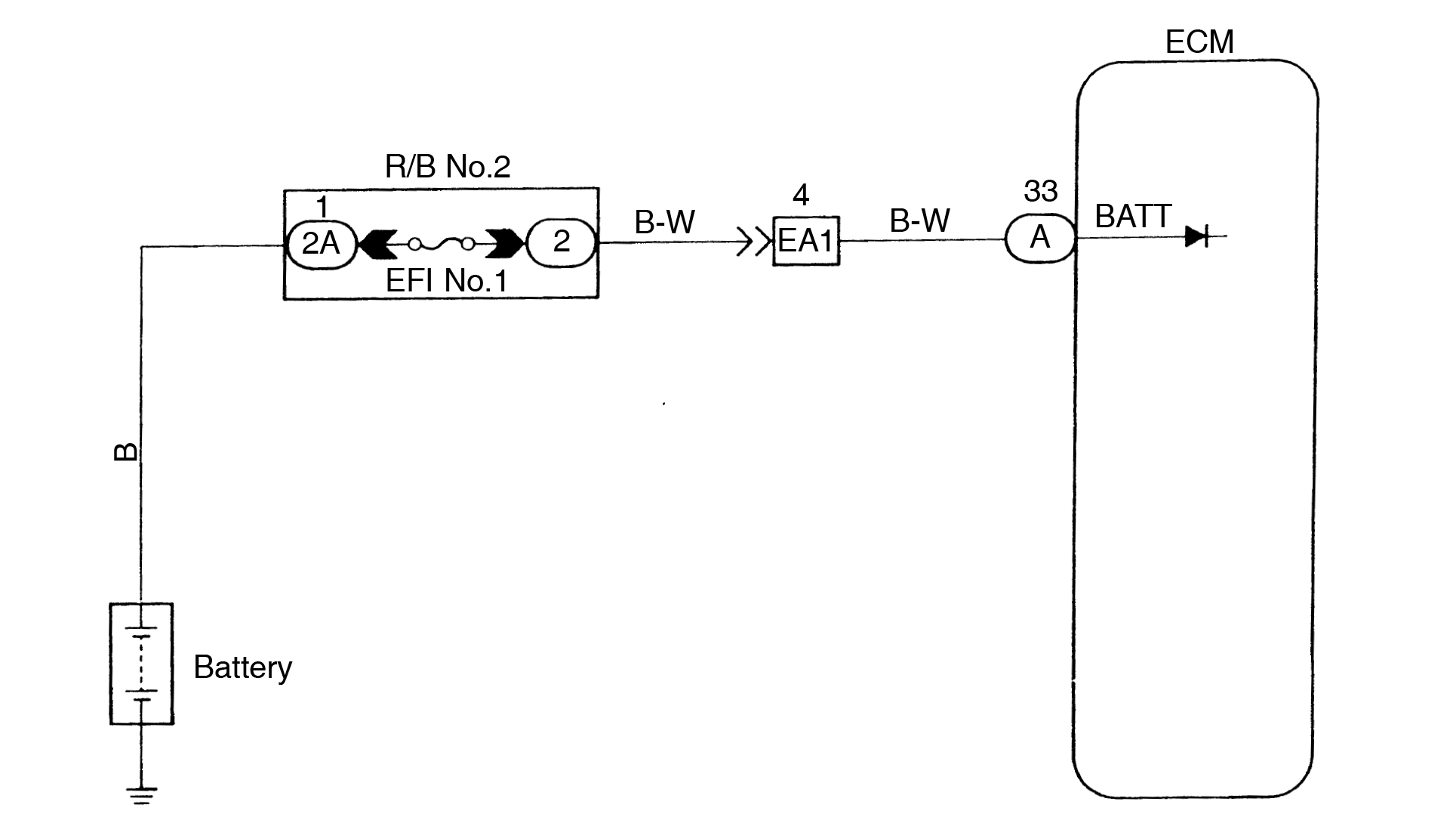
| DTC | P1600 | ECM BATT Malfunction |
Circuit description
Battery positive voltage is supplied to terminal BATT of the ECM even when the ignition switch is OFF for use by the DTC memory and air-fuel ratio adaptive control value memory, etc.
| DTC No. | DTC Detecting Condition | Trouble Area |
| P1600 | Open in back up power source circuit |
|
If DTC P1600 appear, the ECM does not store another DTC.
Wiring diagram
Inspection procedure
| 1 | Check voltage between terminal BATT of ECM connector and body ground. | ||
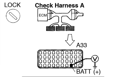 PREPARATION: PREPARATION: Connect Check Harness A (See page DI-20 ). CHECK: Measure voltage between terminal BATT of ECM connector and body ground. OK: Voltage: 9 - 14 V | |||
| OK | Check and replace ECM (See page IN-28 ). | ||
| NG | |||
| 2 | Check EFI fuse. | ||
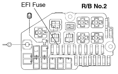 PREPARATION: PREPARATION: Remove EFI fuse from R/B No.2. CHECK: Check continuity of EFI fuse. OK: Continuity | |||
| NG | Check for short in all the harness and components connected to EFI fuse. | ||
| OK | |||
| Check and repair harness or connector between battery, EFI fuse and ECM. | |||
| DTC | P1605 | Knock Control CPU Malfunction |
Circuit description
Refer to Knock Sensor 1, 2 Circuit Malfunction on page DI-65 .
| DTC No. | DTC Detecting Condition | Trouble Area |
| P1605 | Engine control computer malfunction (for knock contorl) |
|
Wiring diagram
Refer to page DI-65 for the WIRING DIAGRAM.Inspection procedure
| 1 | Are there any other codes (besides DTC P1605) being output? | ||
| YES | Go to relevant DTC chart. | ||
| NO | |||
| Check and replace ECM (See page IN-28 ). | |||
| DTC | P1780 | Park/Neutral Position Switch Malfunction |
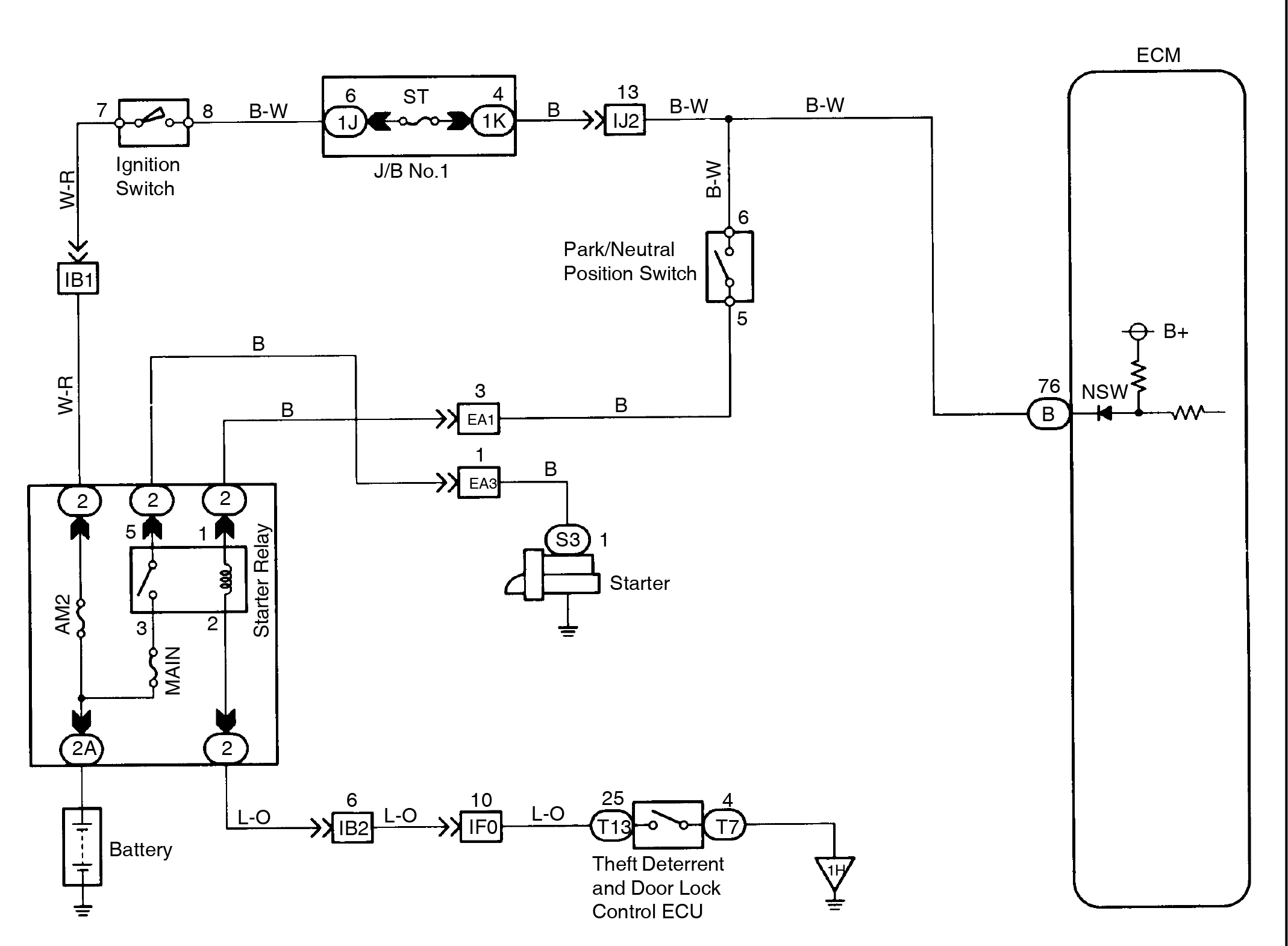
Circuit description
The park/neutral position switch goes on when the shift lever is in the N or P shift position. When it goes on terminal NSW of the ECM is grounded to body ground via the starter relay thus the terminal NSW voltage becomes 0 V. When the shift lever is in the D, 2, L or R position, the park/neutral position switch goes off, so the voltage of ECM terminal NSW becomes battery voltage, the voltage of the ECM internal power source. If the shift lever is moved from the N position to the D position, this signal is used for air-fuel ratio correction and for idle speed control (estimated control), etc.
| DTC No. | DTC Detecting Condition | Trouble Area |
| P1780 | 2 or more switches are ON simultaneously for ”N”, ”2” and ”L” position (2 trip detection logic) |
|
When driving under conditions (a) and (b) for 30 sec. or more the park/neutral position
|
After confirming DTC P1780 use the TOYOTA hand-held tester to confirm the PNP switch signal from ”CURRENT DATA”.
Wiring diagram
Inspection procedure
| 1 | Check park/neutral position switch. | |||||||||||||||||||||||
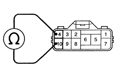 PREPARATION: PREPARATION: Disconnect park/neutral position switch connector. CHECK: Check continuity between each terminal shown below when the shift lever is positioned to each range. OK:
| ||||||||||||||||||||||||
| NG | Replace park/neutral position switch (See page AT-8 ). | |||||||||||||||||||||||
| OK | ||||||||||||||||||||||||
| 2 | Check voltage between terminal NSW of ECM connector and body ground. | |||||||||||||||||||||||
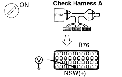 PREPARATION: PREPARATION: Connect Check Harness A (See page DI-20 ). CHECK:
| ||||||||||||||||||||||||
| OK | Check and replace ECM (See page IN-28 ). | |||||||||||||||||||||||
| NG | ||||||||||||||||||||||||
| Check for open and short in harness and connector between ECM and park/neutral position switch (See page IN-28 ). | ||||||||||||||||||||||||
ECM Power Source Circuit |
Circuit description
When the ignition switch is turned ON, battery positive voltage is applied to the coil, closing the contacts of the EFI main relay and supplying power to the terminals +B of the ECM.
Wiring diagram

Inspection procedure
| 1 | Check voltage between terminals +B and E1 of ECM connector. | ||
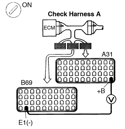 PREPARATION: PREPARATION:
Measure voltage between terminals +B and E1 of ECM connector. OK: Voltage: 9 - 14 V | |||
| OK | Proceed to next circuit inspection shown on matrix chart (See page DI-24 ). | ||
| NG | |||
| 2 | Check for open in harness and connector between terminal E1 of ECM connector and body ground (See page IN-28 ). | ||
| NG | Repair or replace harness or connector. | ||
| OK | |||
| 3 | Check voltage between terminal IGSW of ECM connector and body ground. | ||
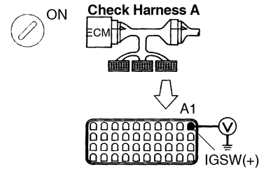 PREPARATION: PREPARATION: Turn ignition switch ON. CHECK: Measure voltage between terminal IGSW of ECM and body ground. OK: Voltage: 9 - 14 V | |||
| OK | Go to step 6. | ||
| NG | |||
| 4 | Check IGN fuse. | ||
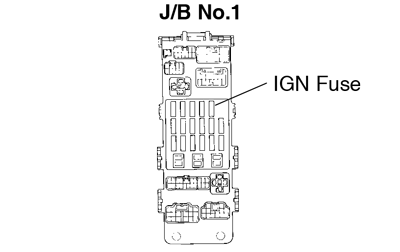 PREPARATION: PREPARATION: Remove IGN fuse from J/B No.1. CHECK: Check continuity of IGN fuse. OK: Continuity | |||
| NG | Check for short in all the harness and components connected to IGN fuse. | ||
| OK | |||
| 5 | Check ignition switch (See page BE-13 ). | ||
| NG | Replace ignition switch. | ||
| OK | |||
| Check for open and short in harness and connector between battery and ignition switch, ignition switch and ECM (See page IN-28 ). | |||
| 6 | Check voltage between terminal M-REL of ECM connector and body ground. | ||
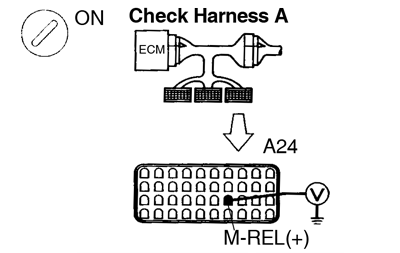 PREPARATION: PREPARATION: Turn ignition switch ON. CHECK: Measure voltage between terminal M-REL of ECM and body ground. OK: Voltage: 9 - 14 V | |||
| NG | Check and replace ECM. | ||
| OK | |||
| 7 | Check EFI fuse (See page DI-128 ). | ||
| NG | Check for short in all the harness and components connected to EFI fuse. | ||
| OK | |||
| 8 | Check EFI main relay (Marking: EFI MAIN) (See page SF-55 ). | ||
| NG | Replace EFI main relay (Marking: EFI MAIN). | ||
| OK | |||
| 9 | Check for open and short in harness and connector between terminal M-REL of ECM connector and body ground (See page IN-28 ). | ||
| NG | Repair or replace harness or connector. | ||
| OK | |||
| Check for open and short in harness and connector between terminal +B of ECM connector and battery (See page IN-28 ). | |||
Fuel Pressure Control Circuit |
Circuit description
The ECM turns on a VSV (Vacuum Switching Valve) to draw the air into the diaphragm chamber of the pressure regulator if it detects that the temperature of the engine coolant is too high during engine staring.
The air drawn into the chamber increases the fuel pressure to prevent fuel vapor lock at high engine temperature in order to help the engine start when it is warm.
Fuel pressure control ends approx. 120 sec. after the engine is started.
Wiring diagram

Inspection procedure
TOYOTA hand-held tester
| 1 | Connect the TOYOTA hand-held tester and check operation of VSV for fuel pressure control. | ||
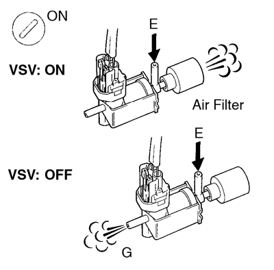 PREPARATION: PREPARATION:
Check operation of VSV when VSV is operated by the TOYOTA hand-held tester. OK: VSV is ON: Air from pipe E flows out through the air filter. VSV is OFF: Air from pipe E flows out through pipe G. | |||
| OK | Check and repair fuel pressure regulator (See page SF-5 ). | ||
| NG | |||
| 2 | Check VSV for fuel pressure control (See page SF-57 ). | ||
| NG | Replace VSV for fuel pressure control. | ||
| OK | |||
| 3 | Check for open and short in harness and connector between EFI main relay (Marking: EFI MAIN) and ECM (See page IN-28 ). | ||
| NG | Repair or replace harness or connector. | ||
| OK | |||
| Check and replace ECM (See page IN-28 ). | |||
OBDII scan tool (excluding TOYOTA hand-held tester)
| 1 | Check VSV for fuel pressure control (See page SF-57 ). | ||
| NG | Replace VSV for fuel pressure control. | ||
| OK | |||
| 2 | Check voltage between terminal FPU of ECM connector and body ground. | ||
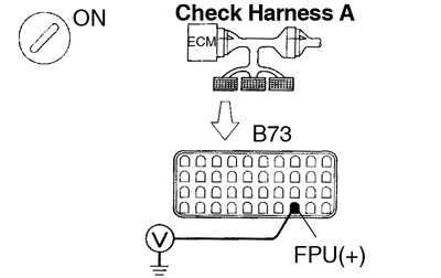 PREPARATION: PREPARATION:
Measure voltage between terminal FPU of ECM connector and body ground. OK: Voltage: 9 - 14 V | |||
| NG | Check for open and short in harness and connector between EFI main relay (Marking: EFI MAIN) and ECM (See page IN-28 ). | ||
| OK | |||
| 3 | Check fuel pressure regulator (See page SF-1 ). | ||
| NG | Repair or replace. | ||
| OK | |||
| Check and replace ECM (See page IN-28 ). | |||
IACV Control Circuit |
Circuit description
This circuit opens and closes the IACV (Intake Air Control Valve) in response to the engine load in order to increase the intake efficiency (ACIS: Acoustic Control Indication System).
When the engine speed is 4,500 rpm or less and the throttle valve opening angle is 30° or more, the ECM turns the VSV ON and closes the IACV. At all other times, the VSV is OFF, so the IACV is open.

Wiring diagram
Inspection procedure
TOYOTA hand-held tester
| 1 | Connect the TOYOTA hand-held tester and check operation of VSV for ACIS. | ||
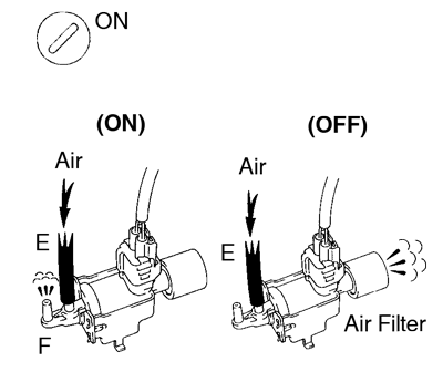 PREPARATION: PREPARATION:
Check operation of VSV when VSV is operated by TOYOTA hand-held tester. OK: VSV is ON: Air from pipe E flows out through pipe F. VSV is OFF: Air from pipe E flows through the air filter. | |||
| OK | Check for vacuum tank (See page SF-50 ). | ||
| NG | |||
| 2 | Check VSV for ACIS (See page SF-63 ). | ||
| NG | Replace VSV for ACIS. | ||
| OK | |||
| 3 | Check for open and short in harness and connector between EFI main relay (Marking: EFI MAIN) and ECM (See page IN-28 ). | ||
| NG | Repair or replace harness or connector. | ||
| OK | |||
| Check and replace ECM (See page IN-28 ). | |||
OBDII scan tool (excluding TOYOTA hand-held tester)
| 1 | Check VSV for ACIS (See page SF-63 ). | ||
| NG | Replace VSV for ACIS. | ||
| OK | |||
| 2 | Check voltage between terminal ACIS of ECM connector and body ground. | ||
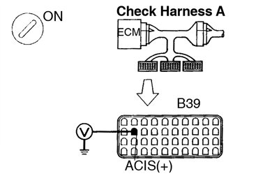 PREPARATION: PREPARATION:
Measure voltage between terminal ACIS of ECM connector and body ground. OK: Voltage: 9 - 14 V | |||
| NG | Check for open and short in harness and connector between EFI main relay (Marking: EFI MAIN) and ECM (See page IN-28 ). | ||
| OK | |||
| 3 | Check for vacuum tank (See page SF-50 ). | ||
| NG | Repair or replace. | ||
| OK | |||
| Check and replace ECM (See page IN-28 ). | |||
This guide is based on the book edition Toyota (RM502U, 1997)